


Quick Research
Generate reliable direction feasibility study reports for your R&D in just a few steps.

Technical Q&A
Discover and master advanced knowledge NOW. Basics, ideas, possibilities, all at once.

Find Solutions
As an expert in R&D theories, this can generate solutions to your technical problems instantly.

Evaluate Feasibility
Analyze your overall solution with one click, know your potential R&D risks in advance.

Monitor Landscape
Get weekly tech updates, stay abreast of the latest tech innovations and key insights.
Manufacturing method of DC electric machine carbon brush holder
A production method and technology of DC motor, applied in the direction of circuits, current collectors, electrical components, etc., can solve the problems of poor riveting, low production efficiency, insufficient pull-off force, etc., and achieve the effect of reducing leftovers, high production efficiency, and providing utilization rate
- Summary
- Abstract
- Description
- Claims
- Application Information
AI Technical Summary
Problems solved by technology
Method used
Image


Examples
Embodiment 1
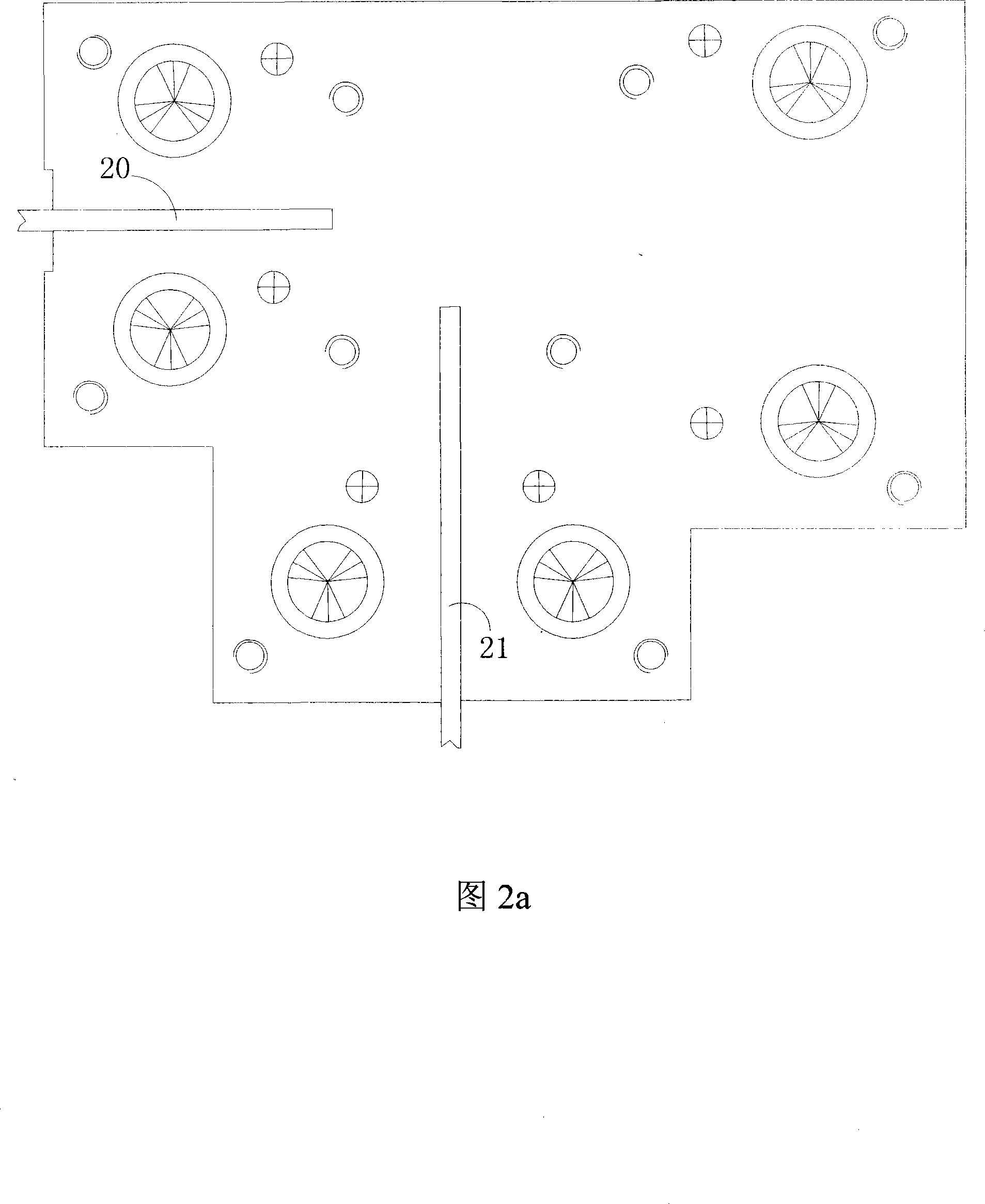
[0025] With reference to Fig. 2a-Fig. 2e, comprise the following steps:
[0026] Referring to Fig. 2a, the brass strip 20 used to make the terminal is installed in the terminal feeding guide rail on the worktable, and the beryllium copper strip 21 used to make the elastic arm is installed in the elastic arm feeding guide rail on the workbench at the same time , the two guide rails can be at an angle of 10°-90° and intersect. The choice of the angle can be based on the size of the material. What this embodiment uses is that the brass material strip 20 is located in the transverse direction of the workbench, and the beryllium copper material strip 21 is located on the workbench. The longitudinal direction, the two form an angle of 90 degrees, and a riveting stamping die is provided at the intersection of the two;
[0027] Referring to Fig. 2 b, before the brass strip 20 and the beryllium copper strip 21 move to the riveting stamping die, the brass strip 20 and the beryllium copp...
Embodiment 2
[0030] Embodiment 2, with reference to Fig. 3, for wider beryllium copper strip 21, can make the beryllium copper strip 21 of elastic arm and the brass strip 20 of making terminal form an angle of 45 degrees, all the other are the same as embodiment 1.
PUM
 Abstract
Description
Claims
Application Information
 - R&D Engineer
- R&D Manager
- IP Professional
- Industry Leading Data Capabilities
- Powerful AI technology
- Patent DNA Extraction
Browse by: Latest US Patents, China's latest patents, Technical Efficacy Thesaurus, Application Domain, Technology Topic, Popular Technical Reports.
© 2024 PatSnap. All rights reserved.Legal|Privacy policy|Modern Slavery Act Transparency Statement|Sitemap|About US| Contact US: help@patsnap.com