
Friction clutch for at least one running wheel of a track-bound traction vehicle

A technology of rotating wheels and clutches, which is applied to transmissions driven by electric motors, slip couplings, couplings, etc., and can solve problems such as inability to adjust sliding clutches, difficult access to repairs or maintenance, and complicated preparation methods. , achieve the effect of shortening maintenance time, simplifying disassembly work and easy access

Inactive Publication Date: 2008-04-09
SIEMENS MOBILITY GMBH
View PDF0 Cites 6 Cited by
  • Summary
  • Abstract
  • Description
  • Claims
  • Application Information

AI Technical Summary

Problems solved by technology

[0007] However, its disadvantages are that the known slip clutch is composed of many parts, the preparation method is relatively complicated, and because it is installed near the electric motor, it is difficult to repair or maintain was touched
In addition, subsequent adjustment of known slip clutches with respect to the maximum transmission torque is also not possible

Method used


Image

  • Friction clutch for at least one running wheel of a track-bound traction vehicle
  • Friction clutch for at least one running wheel of a track-bound traction vehicle
  • Friction clutch for at least one running wheel of a track-bound traction vehicle

Examples


Embodiment Construction

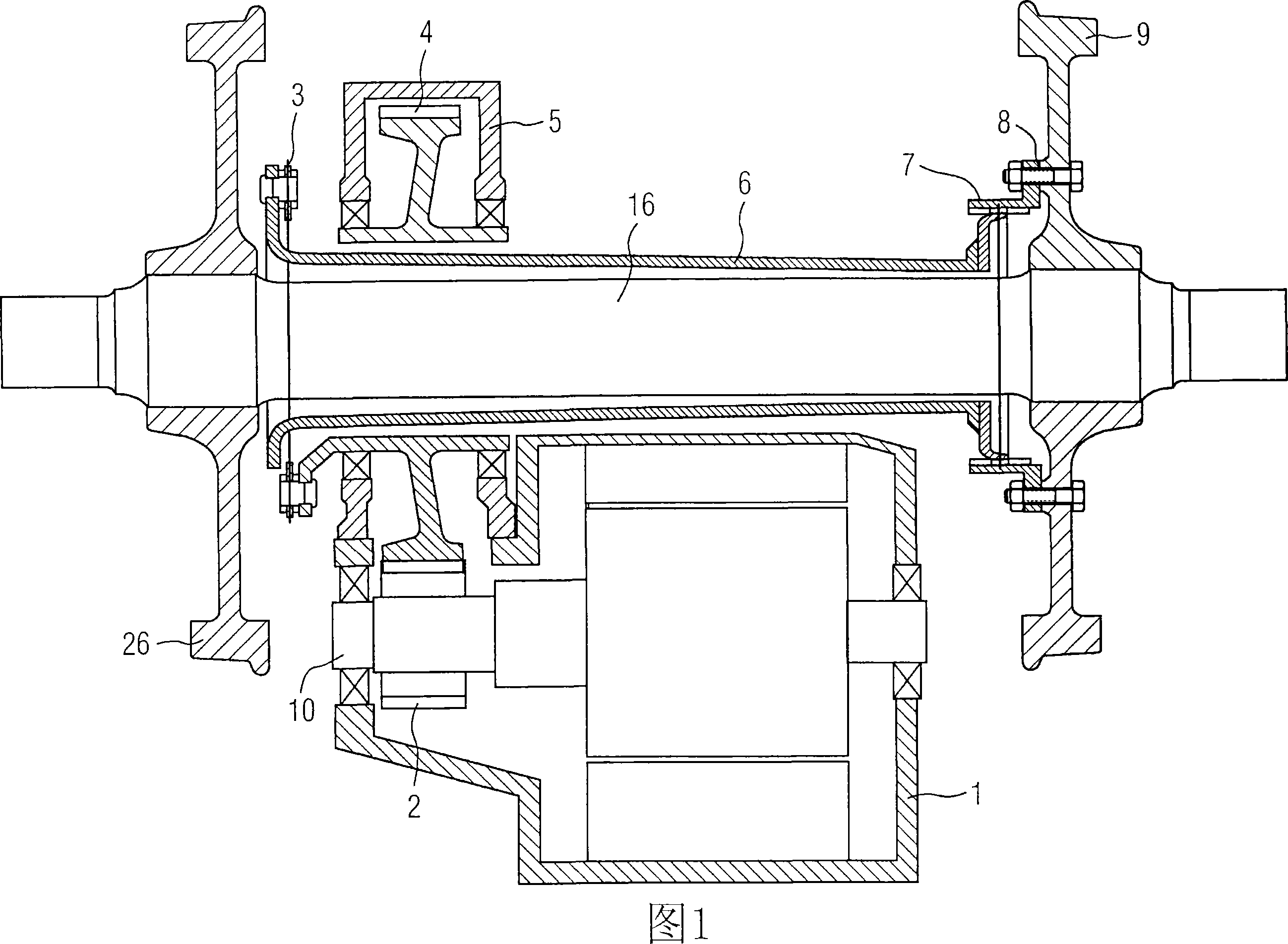
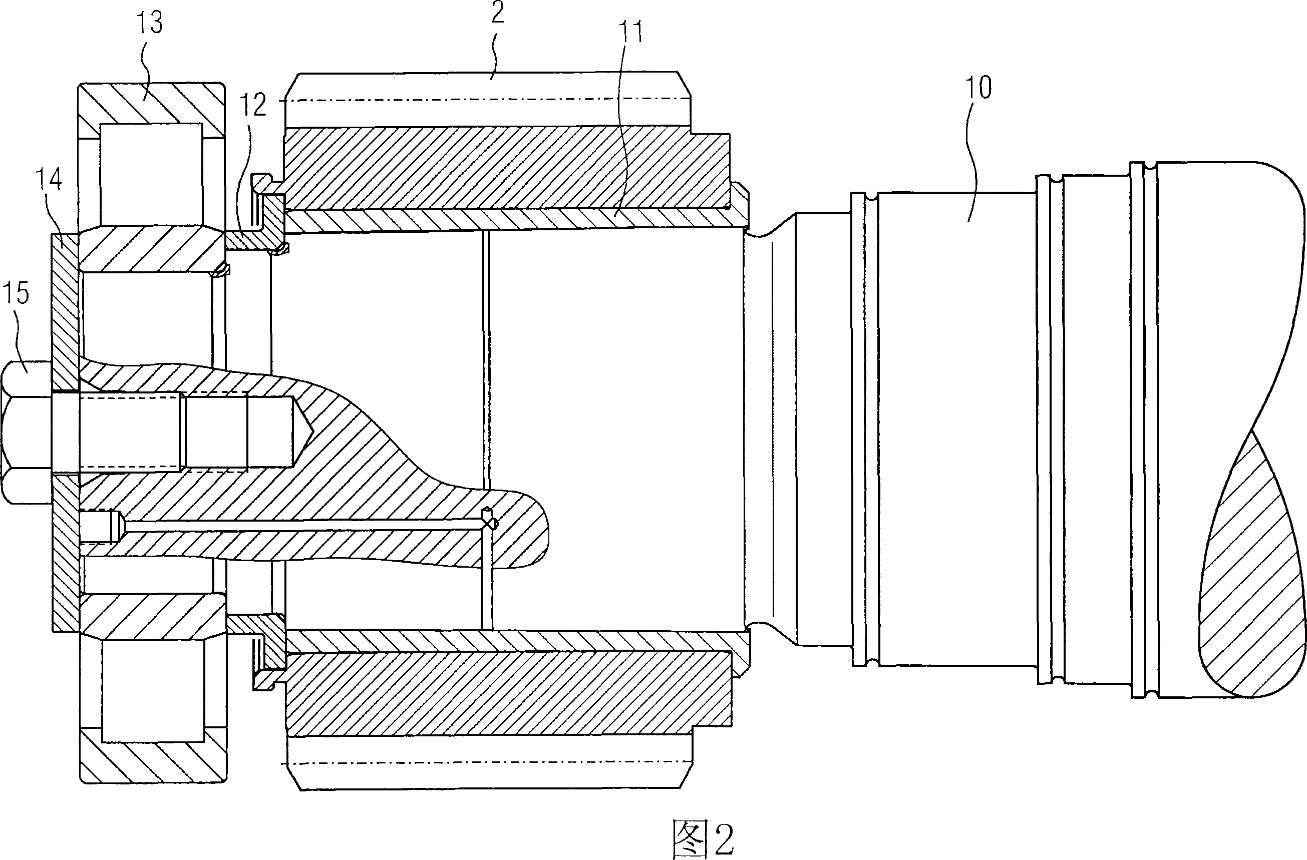
[0029] Figure 1 shows the drive train of a prior art railcar. A traction motor 1 drives an electric pinion 2 fixed on a motor shaft 10 . The electric pinion 2 is connected via its tooth flanks to a transmission bull gear 4 mounted in a single-stage transmission 5 . The drive gear wheel 4 is connected via a drive-side axial clutch joint 3 to an axial clutch hollow shaft 6 , which in turn is connected to a running wheel-side axial clutch joint 7 . The axial clutch coupling 7 on the runner side is connected to the runner 9 via a flange screw connection 8 . The rotating wheel 9 is connected on an axle 16, and another rotating wheel 26 is installed on the other end of the axle 16. Wherein, the function of the axial clutch hollow shaft 6 is also to realize the suspension, so as to avoid the undesired rigid coupling between the traction motor and the running wheel. Such drive trains in the prior art must be oversized in order to prevent failures caused by short-circuit surge torqu...


PUM


Abstract

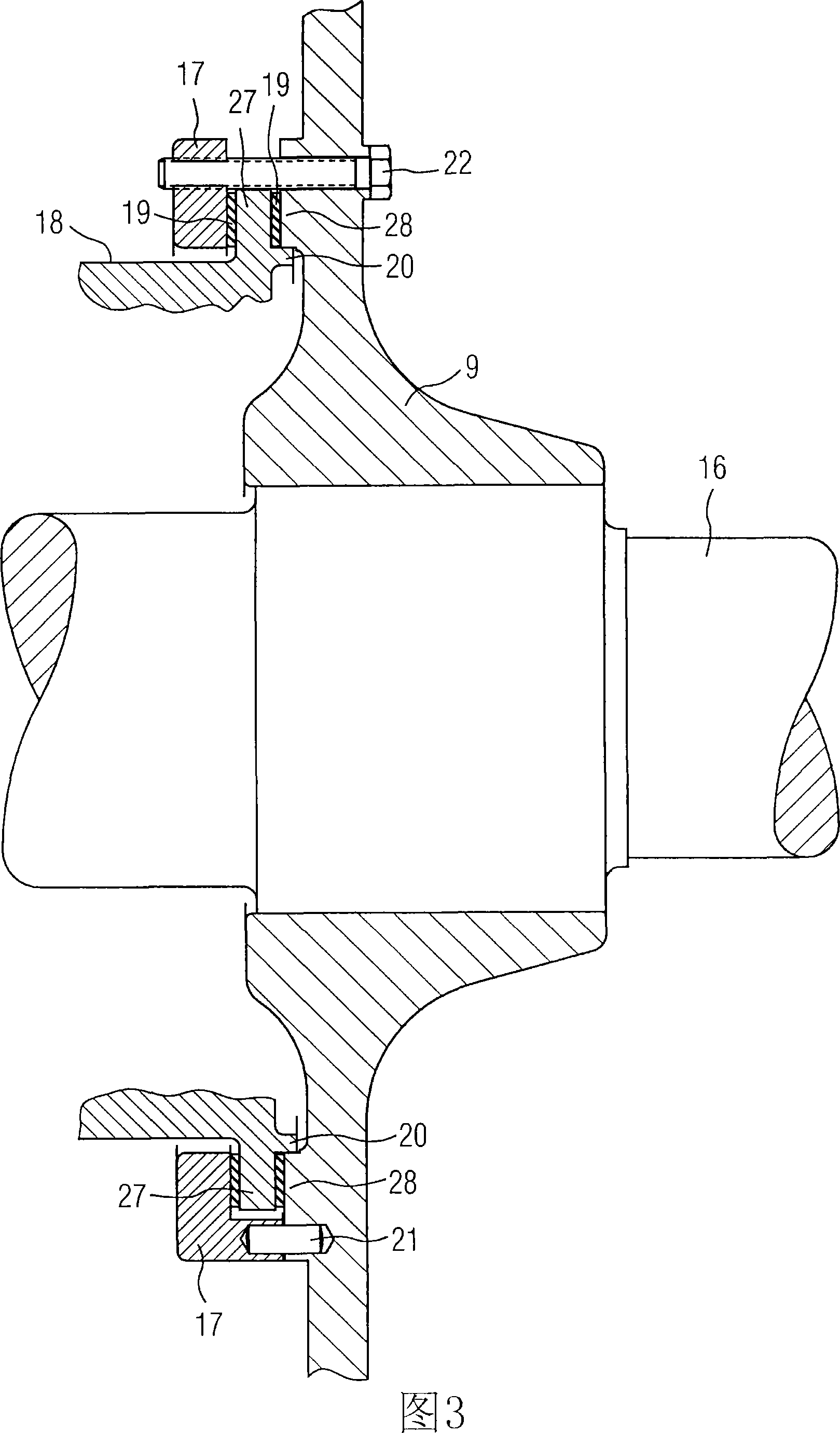
The invention relates to a slip clutch for at least one railcar running wheel (9) fixed to a shaft (16) and driven by an electric motor (1), said slip clutch having oppositely arranged annular outer teeth, wherein the outer teeth of the slip clutch are composed of a part (28) of the rotating wheel (9) and a compression ring (17, 23), the compression ring (17, 23 ) is fixedly connected with the rotating wheel (9), and a clamping ring (27) is clamped between the compression rings (17, 23) and the parts (28) of the rotating wheel (9). The slip clutch provided by the present invention is easy to prepare and easy to access. In addition, a subsequent adjustment of the maximum torque is possible.

Description

technical field [0001] The invention relates to a slip clutch for at least one running wheel of a rail vehicle, wherein said running wheel is fixed on a shaft and can be driven by an electric motor. Background technique [0002] The current electric drive devices for rail cars generally use three-phase asynchronous motors connected with power converters. When the control device of the converter fails, the three-phase asynchronous motor will generate a large braking torque in a short time, which is many times the maximum working torque, also known as "short-circuit impact torque". ". The resulting sudden braking places a high load on the entire drive train. [0003] Trams use drive shafts for transmitting drive or braking torques to the wheelsets or to the individual running wheels, which drive shafts respectively connect a drive mounted, for example, in a bogie or in a carriage to the running wheels. When the drive is suspended, this axial coupling must compensate for the...

Claims


Application Information

Patent Timeline
Patent Type & Authority Applications(China)
IPC IPC(8): F16D7/02B61C9/50
CPCB61C9/44F16D7/024
Inventor 克劳斯·朱斯伯恩德·普范施密特
Owner SIEMENS MOBILITY GMBH
Learn More