Water filtration purifier and method thereof
A purification device and water filtration technology, which is applied to chemical instruments and methods, filtration circuits, filtration separation, etc., can solve the problems of high production cost and magnet production cost, and achieve high water purification effect
- Summary
- Abstract
- Description
- Claims
- Application Information
AI Technical Summary
Problems solved by technology
Method used
Image
Examples
Embodiment 1
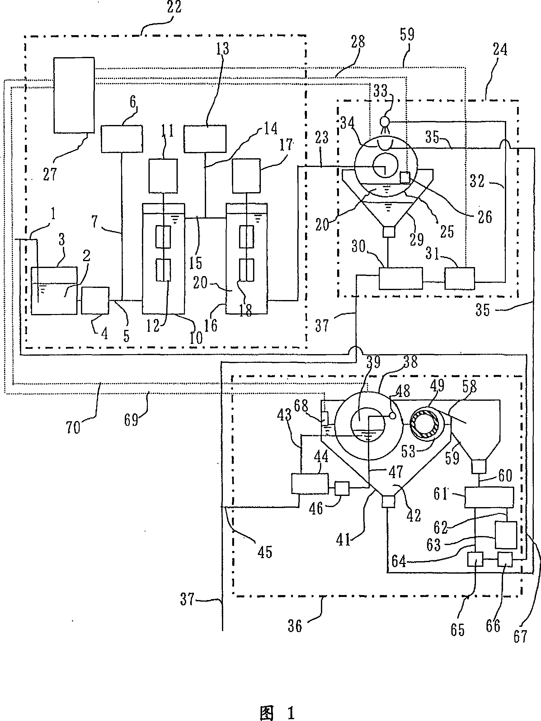
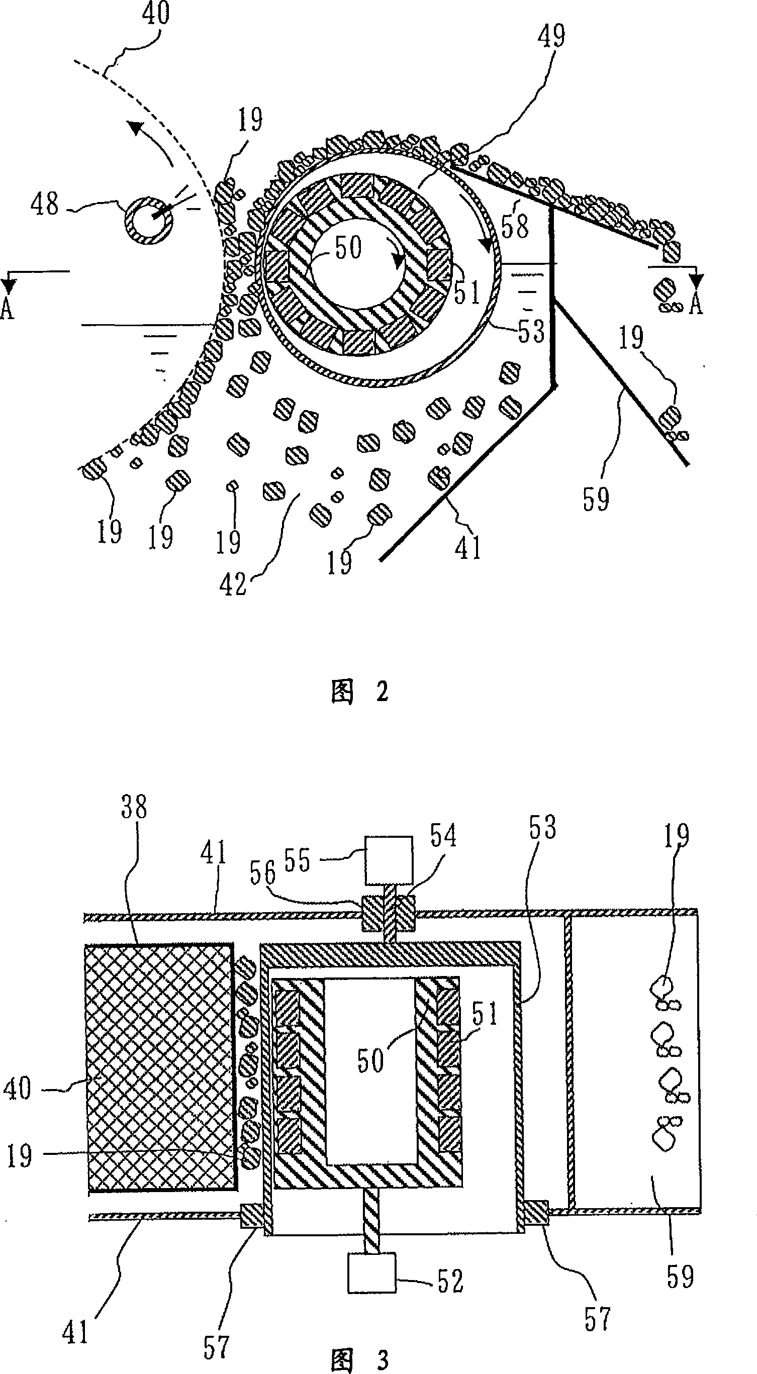
[0020] Hereinafter, the details of an embodiment of the present invention will be described with reference to the accompanying drawings 1 , 2 and 3 . In addition, FIG. 2 is an enlarged sectional view of the magnetic separator 36 shown in FIG. 1 , and FIG. 3 is an A-A sectional view of the aforementioned FIG. 2 .
[0021] First of all, Fig. 1 shows the overall schematic mechanism of the water filtration and purification device of the present invention. In the figure, the raw water 2 supplied from the pipeline 1 is first stored in the raw water storage tank 3. Here, the garbage with a size of several microns is removed. Raw water 2 , which is water to be treated, such as oil particles, organic matter, and microorganisms, is used to send a predetermined amount to pipe 5 again by pump 4 . At this time, from the seeding agent adjustment device 6 through the conduit 7, add magnetic powder such as ferroferric oxide and pH regulators in the above-mentioned pipeline 5, and also provide...
Embodiment 2
[0045] Fig. 5 shows another embodiment (Embodiment 2) of the present invention. The difference between this embodiment and the above-mentioned embodiment is that, especially from the comparison with the above-mentioned FIG. The connected flow path 68 allows purified treated water to flow into the pipe 43 . In addition, the treated water passed through the pipe 43 is accumulated in the purified water tank 44 of FIG. 1 , merged into the pipe 37 through the pipe 45 , and then discharged out of the system.
[0046] On the other hand, in this embodiment 2, while the sludge water 42 flowing into the magnetic separator 36 through the pipeline 35 flows in the flow path 71, its magnetic floc 19 is attracted by the magnetic force of the permanent magnet 51, and is adhered by the magnetic force. on the outer surface of the rotating body 53 . Then, the group of magnetic flocs 19 adhering to the surface of the rotating body 53 moves into the atmosphere by the rotation of the rotating bod...
Embodiment 3
[0049] 6 and 7 show another embodiment of the present invention (Embodiment 3). The difference between this embodiment and the above-mentioned first embodiment is that, especially in comparison with the above-mentioned FIG. 2 , the magnet 69 is composed of a superconducting magnet, and the length A between the ends of the magnet is further shortened. In addition, the superconducting magnet 69 includes: a vacuum container 70 for heat insulation; a heat conductor 72 with a superconductor 71 built in; a cold engine 73 for cooling the end of the heat conductor 72 in the vacuum container 70; A compressor 75 of the cold engine 73; and a pipeline 76 for recovering the medium-pressure gas adiabatically expanded by the cold engine 73 to the compressor. Moreover, the magnet 69 is fixedly supported by a support member 77 fixed on the water tank 41 .
[0050] In addition, these figures show a state where the superconductor 71 has already been magnetized by an external magnet, cooled to a...
PUM
 Abstract
Description
Claims
Application Information
 - R&D
- Intellectual Property
- Life Sciences
- Materials
- Tech Scout
- Unparalleled Data Quality
- Higher Quality Content
- 60% Fewer Hallucinations
Browse by: Latest US Patents, China's latest patents, Technical Efficacy Thesaurus, Application Domain, Technology Topic, Popular Technical Reports.
© 2025 PatSnap. All rights reserved.Legal|Privacy policy|Modern Slavery Act Transparency Statement|Sitemap|About US| Contact US: help@patsnap.com


