Apparatus and method for processing elevator wire rope groove

A groove processing and steel cable technology, which is applied in the direction of metal processing equipment, elevators in buildings, grinding/polishing safety devices, etc., can solve the problems of not considering the refurbishment processing, deflector wheel refurbishment processing, etc., Achieve the effects of suppressing tool replacement frequency, preventing deterioration of machining accuracy, and improving efficiency

Active Publication Date: 2011-01-12
MITSUBISHI ELECTRIC BUILDING SOLUTIONS CORP
View PDF1 Cites 0 Cited by
  • Summary
  • Abstract
  • Description
  • Claims
  • Application Information

AI Technical Summary

Problems solved by technology

[0013] The groove shape measuring device of the prior art sheave does not take into account that the main cable 2 can be effectively refurbished without removing the main cable 2 from the drive cable pulley, and does not consider the deflector even if there is no drive device. Wheels can also be refurbished

Method used


Image

  • Apparatus and method for processing elevator wire rope groove
  • Apparatus and method for processing elevator wire rope groove
  • Apparatus and method for processing elevator wire rope groove

Examples


Embodiment approach 1

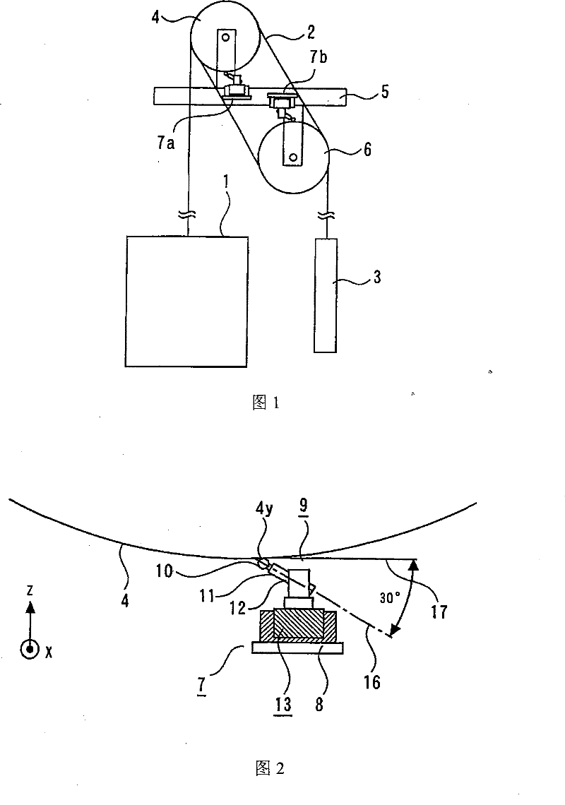
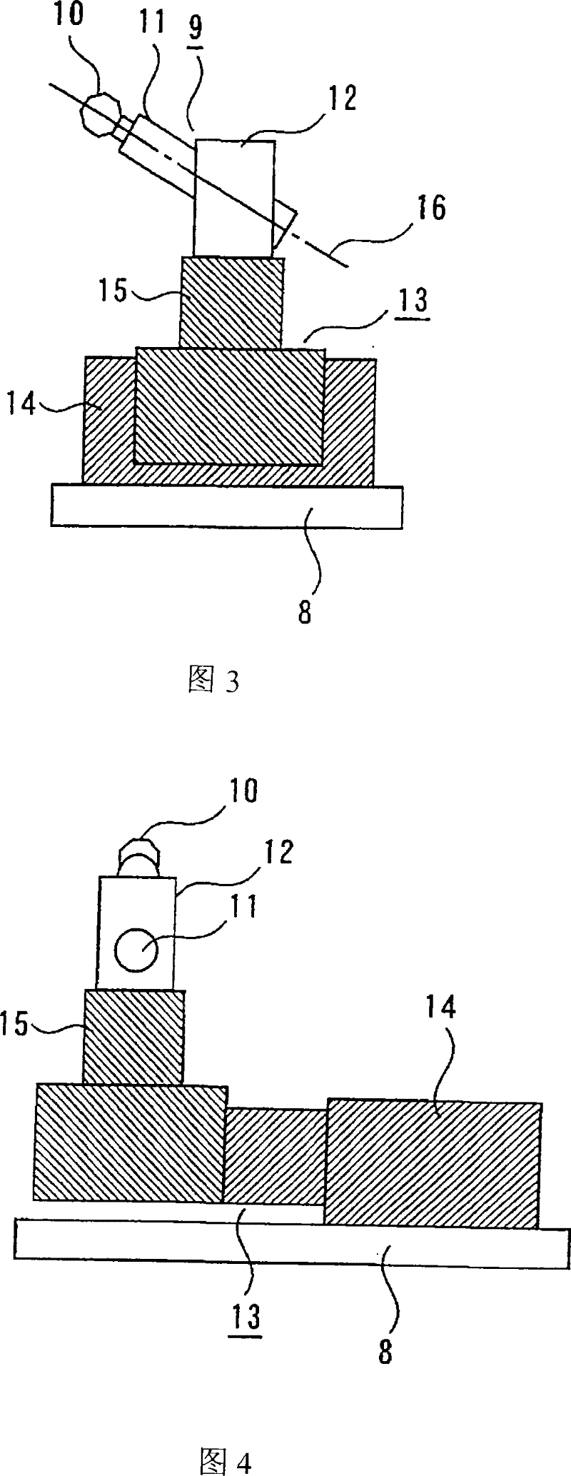
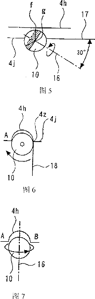
[0073] figure 1 It is a schematic configuration diagram of an elevator apparatus in a state where the elevator cable groove processing apparatus according to Embodiment 1 of the present invention is installed; figure 2 It is a side view showing the installation of the elevator cable groove processing device in Embodiment 1 of the present invention; image 3 It is a side view for explaining the movable state of the movable support part of the cable groove processing device in Embodiment 1 of the present invention; Figure 4 It is a rear view for explaining the movable state of the movable support part of the cable groove processing device in Embodiment 1 of the present invention; Figure 5 It is a side view when the angle between the rotation axis of the processing part and the tangent line at the processing point on the driving cable pulley is 30 degrees; Figure 6 It is the front view when the angle between the rotation axis of the processing part and the tangent line at ...

Embodiment approach 2

[0094] Figure 8 It is a side view of the elevator cable groove processing device in Embodiment 2 of the present invention, Figure 9 It is a front view of the cable groove processing device in Embodiment 2 of the present invention, Figure 10 It is a rear view of the cable groove processing device in Embodiment 2 of the present invention, Figure 11 It is a flowchart showing the steps of controlling the feed amount according to the position measurement value of the elevator cable groove processing device in Embodiment 2 of the present invention, Figure 12 is a flow chart showing the steps of controlling the feed rate according to the measured temperature value, Figure 13 It is a flow chart showing the procedure for controlling the feed rate according to the load measurement value. In the figure, the same or equivalent parts as those in Embodiment 1 are given the same reference numerals, and description thereof will be omitted.

[0095] In Embodiment 2, the processing ef...


PUM


Abstract

The invention provides a processing device for an elevator steel cable groove which can renovate and process the steel cable groove used for driving a steel cable wheel in a short time, and can prevent the service quality of the elevator from decreasing. The invention is provided with a mounting part (8) which is demountably arranged on a fixing rack (5) of the elevator, a processing part (9) which is arranged at the opposite position of the steel cable groove part of a main steel cable (2) being used for suspension hanging the case of the elevator and being positioned inside the steel cable groove (4a) of a driving steel cable wheel (4), and a movable bearing part (13) which is arranged on the mounting part and used for bearing the processing part and which can move along the rotating axle direction and the radius direction of the driving steel cable wheel. The processing part is provided with a rotary grinding wheel (10) which is used for grinding and processing the steel cable groove. The rotary axle (16) of grinding wheel forms an angle of about 30 degrees with a tangent (17) starting from the processing point of the driving steel cable wheel.

Description

technical field [0001] The present invention relates to an elevator cable groove machining device and a machining method thereof for efficiently refurbishing a cable groove formed on a driving sheave or a deflector sheave of an elevator winch. Background technique [0002] Figures 14 to 17 Shows the existing elevator steel cable groove processing device, Figure 14 It is a schematic configuration diagram of a general elevator arrangement, Figure 15 It is a schematic configuration diagram of the drive cable pulley of the elevator winch, Figure 16 It is a schematic configuration diagram of the case where the worn cable groove of the drive cable pulley is reprocessed with the existing cable groove processing device, Figure 17 It is a schematic configuration diagram showing the finished state. [0003] Figure 14 Among them, 1 is the hanging box of the elevator, and 2 is the main steel cable of the suspension hanging box 1, and one end of the main steel cable is fixed on...

Claims


Application Information

Patent Timeline
Patent Type & Authority Patents(China)
IPC IPC(8): B24B19/02B24B23/08
CPCB24B19/02B24B49/00B24B49/14B24B55/06B66B11/08
Inventor 长谷川正彦中筋智明本田武信飞田晃
Owner MITSUBISHI ELECTRIC BUILDING SOLUTIONS CORP
Why Eureka
Try Eureka