
Correction method for position signal phase error of brushless DC motor without position sensor

A brush DC motor and signal phase technology, which is applied in the field of brushless DC motor position signal phase error correction, can solve the problems of motor operation performance impact, delay calculation of phase error, etc., and achieve good real-time performance and simple effect

Inactive Publication Date: 2008-04-02
NANJING UNIV OF AERONAUTICS & ASTRONAUTICS
View PDF0 Cites 29 Cited by
  • Summary
  • Abstract
  • Description
  • Claims
  • Application Information

AI Technical Summary

Problems solved by technology

In this type of method, factors such as low-pass filter phase shift, delay calculation error, and armature reaction cause phase errors in the measured position signal, which affects the operating performance of the motor.

Method used


Image

  • Correction method for position signal phase error of brushless DC motor without position sensor
  • Correction method for position signal phase error of brushless DC motor without position sensor
  • Correction method for position signal phase error of brushless DC motor without position sensor

Examples


Embodiment Construction

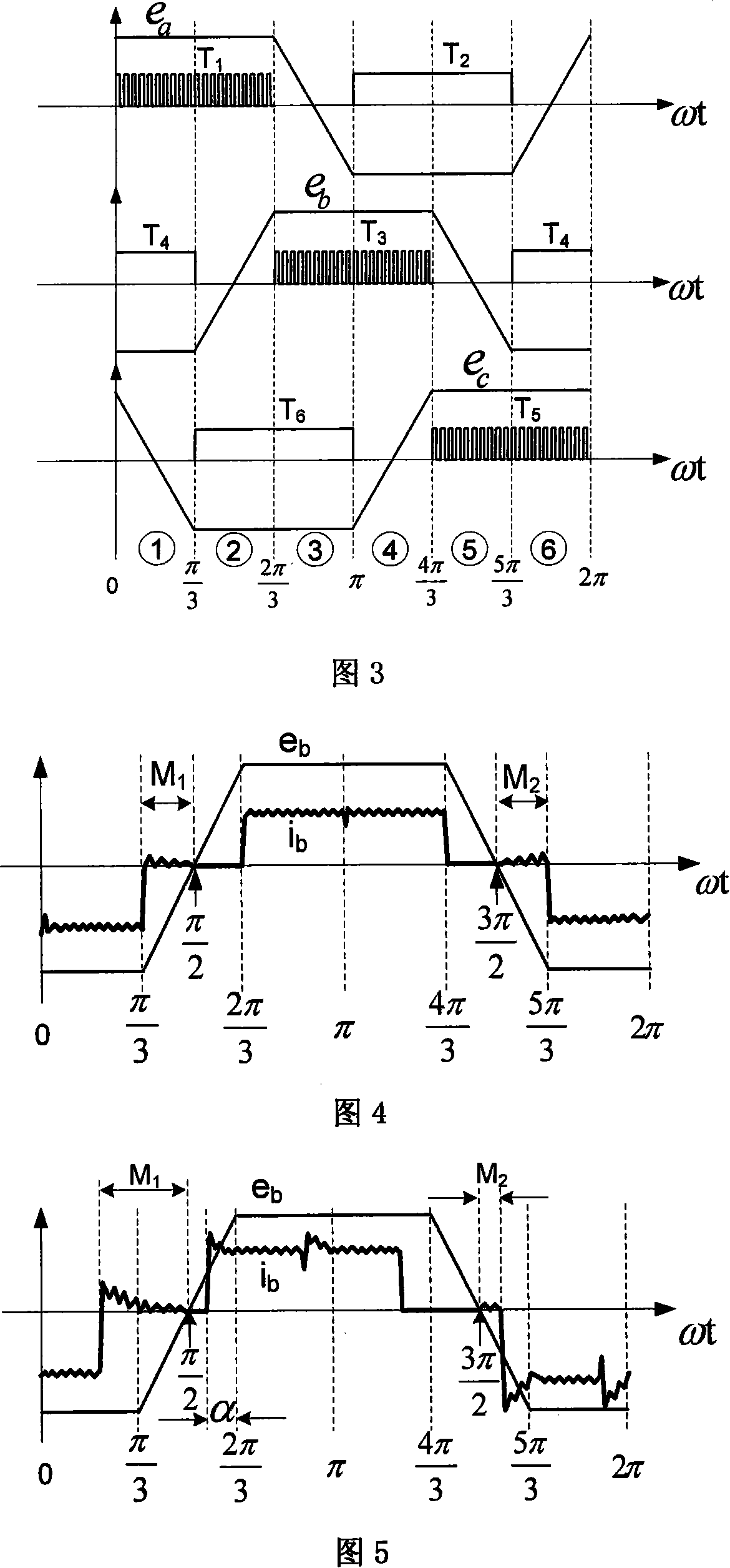
[0017] When the H_pwm-L_on modulation method (see Figure 3) is used, there is a freewheeling current in the non-conducting part of the brushless DC motor corresponding to the counter electromotive force less than zero. Let the freewheeling part in the 60° non-conduction working interval after the negative 120° conduction interval of the motor phase winding be M 1 In the working interval, the freewheeling part in the 60° non-conducting working interval after the forward 120° conduction interval of the phase winding is M 2 working area.

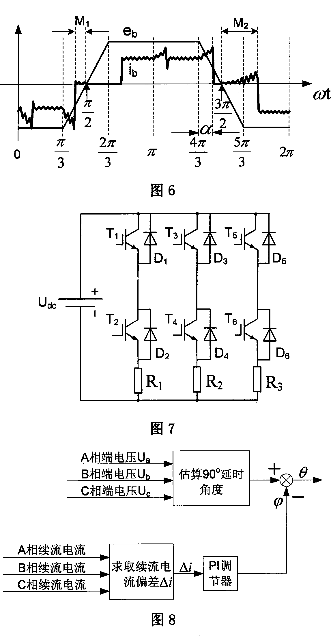
[0018] Let M 1 The average value of freewheeling current in the interval is I m1 ,M 2 The average value of freewheeling current in the interval is I m2 , Δi=I m2 -I m1 . I m1 , I m2 Has the following relationship: when the motor commutates accurately, I m1 =I m2 , Δi=0 (see Figure 4); when commutating ahead, I m1 > I m2 , Δim1 m2 , Δi>0, Δi increases as the lag commutation angle increases (see Figure 6). According to this characte...


PUM


Abstract

The present invention relates to a method for correcting the phase error of the position signal of the no-position transducer brushless DC motor, which belongs to the method for correcting the phase error of the position signal of brushless DC motor. The correcting method controls a first afterflow current average value of the afterflow part in the 60 degree non-conductive interval after the negative 120 degree conductive interval of the electric motor phase winding same to a second afterflow current average value of the afterflow part in the 60 degree non-conductive working interval after the positive interval of the electric motor phase winding, to realize the phase error compensation of the position signal of the no-position transducer brushless DC motor. The specific method is measuring respectively the current average values of the two currents of the first current and the second current, inputting the deviation value of the average value of the two afterflow currents of the first and the second afterflow current as the feedback quantity to the PI regulator, and regulating the average value of the first current afterflow current equal to the average value of the second current afterflow current through the PI regulator. The correcting method can automatically correct the phase error of the position signal of the no-position transducer brushless DC motor, the realization is easy and the real-time property to the phase error of the position error is good.

Description

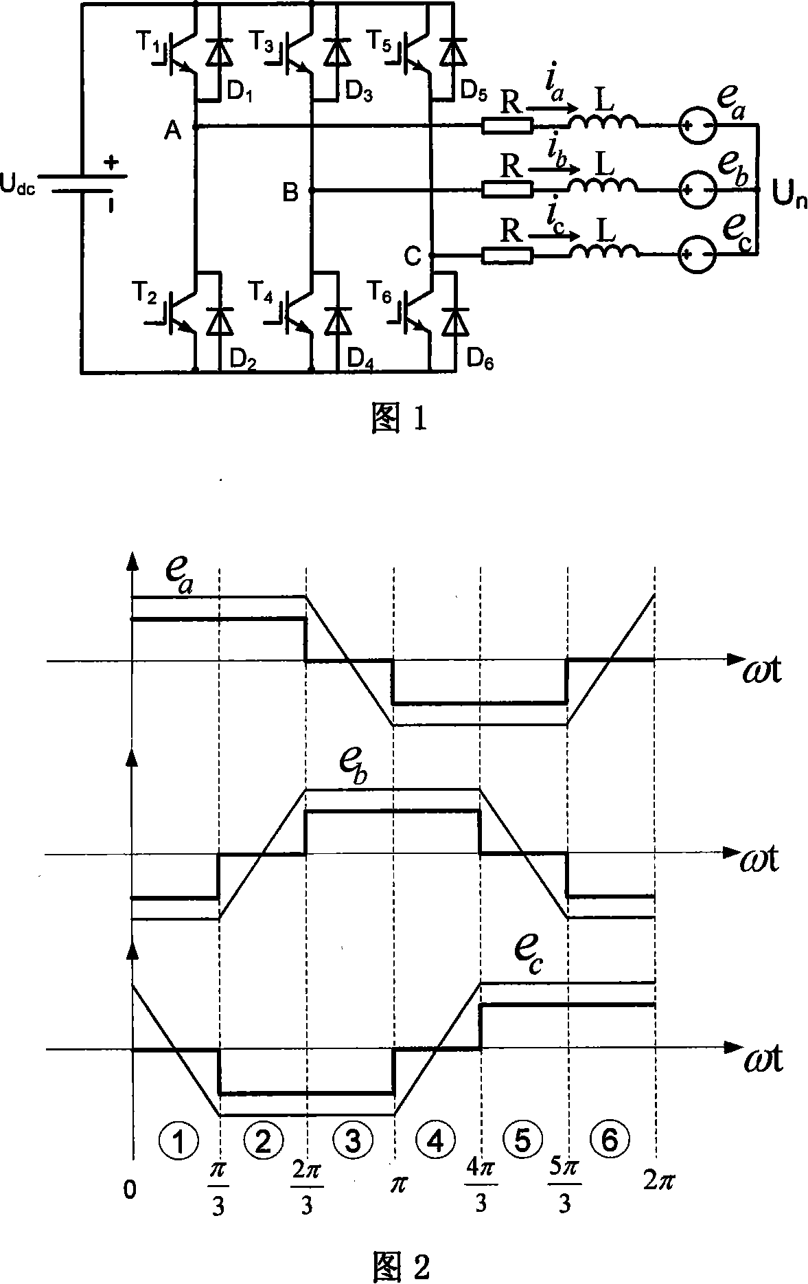
technical field [0001] The invention relates to a method for correcting a phase error of a position signal of a brushless direct current motor. Background technique [0002] Brushless DC motors have the advantages of simple structure, convenient control, high reliability, high power density, and high efficiency, and have been applied in many industrial fields. Usually, it obtains the position signal of the rotor by means of the position sensor, but the brushless DC motor with the rotor position sensor has a series of disadvantages such as large motor size, easy interference from the signal line of the position sensor, low reliability of the sensor, and high requirements for installation accuracy. Applications are subject to certain restrictions. Therefore, sensorless brushless DC motors have attracted widespread attention. [0003] Ordinary brushless DC motors are powered by a three-phase voltage inverter, and their stator windings are star-connected (see Figure 1), the co...

Claims


Application Information

Patent Timeline
Patent Type & Authority Applications(China)
IPC IPC(8): H02P6/18G01R31/34G05F5/00
Inventor 宋飞周波吴小婧
Owner NANJING UNIV OF AERONAUTICS & ASTRONAUTICS
Learn More