
Force induced switch and its application

A technology of inductive switch and contact switch, which is applied in the field of switch control devices, can solve the problems of unreliable contact of electrode sheets, easy aging of elastic insulating layer, and low reliability of use, and achieve reliable and accurate positioning and shooting, compact switch structure, Precisely tested and controlled effects

Inactive Publication Date: 2008-04-02
NINGBO HAISHU SIFANG ELECTRONICS
View PDF2 Cites 12 Cited by
  • Summary
  • Abstract
  • Description
  • Claims
  • Application Information

AI Technical Summary

Problems solved by technology

Although the gravity switch of the described structure is simple in structure, the elastic insulating layer is easy to age and has poor elasticity after a long time of use, and the contact between the electrode pads is not reliable, and if people forget to take away the items when they leave, the items will be heavy. The insulation layer is still in a compressed state, and the power supply is still on, which cannot achieve the effect of people walking off the power, and the reliability of use is not high.
[0005] Therefore, the force-sensing switches of the above two patents all have certain defects and deficiencies, and still need to make better improvements.

Method used


Image

  • Force induced switch and its application
  • Force induced switch and its application
  • Force induced switch and its application

Examples


Embodiment Construction

[0032] The present invention will be further described in detail below in conjunction with the accompanying drawings and embodiments.

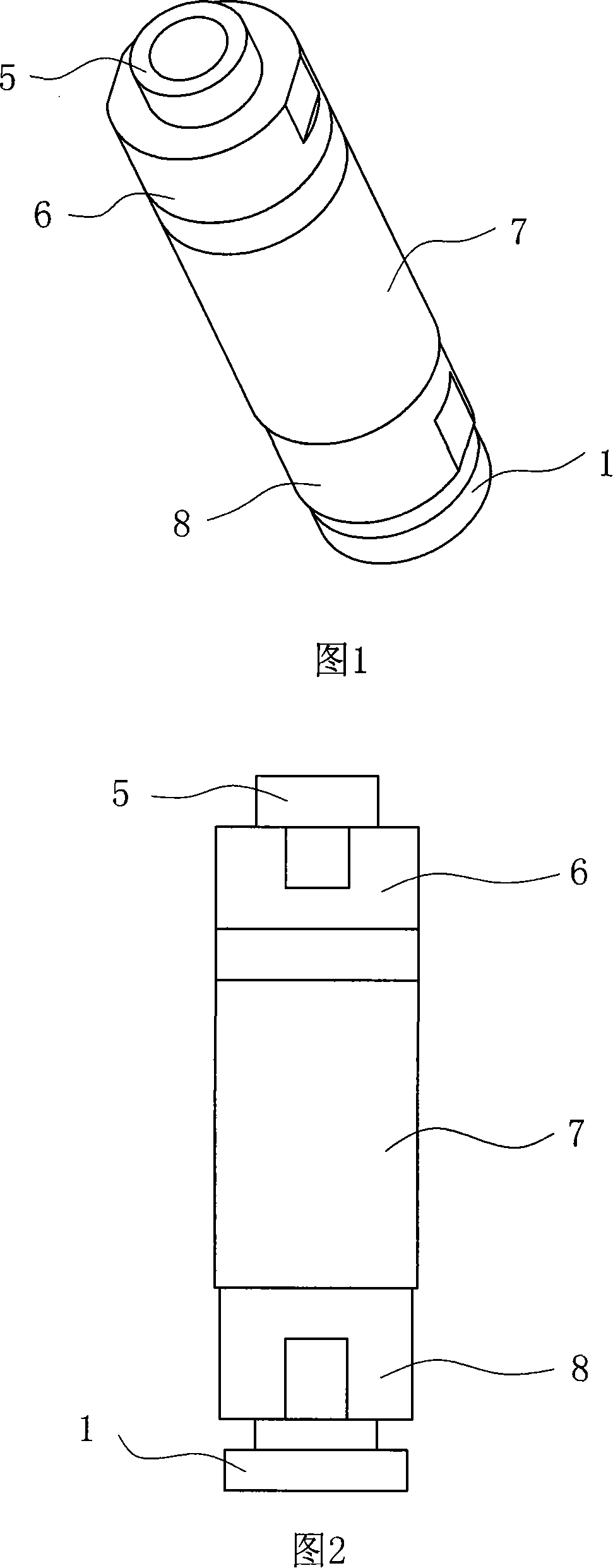
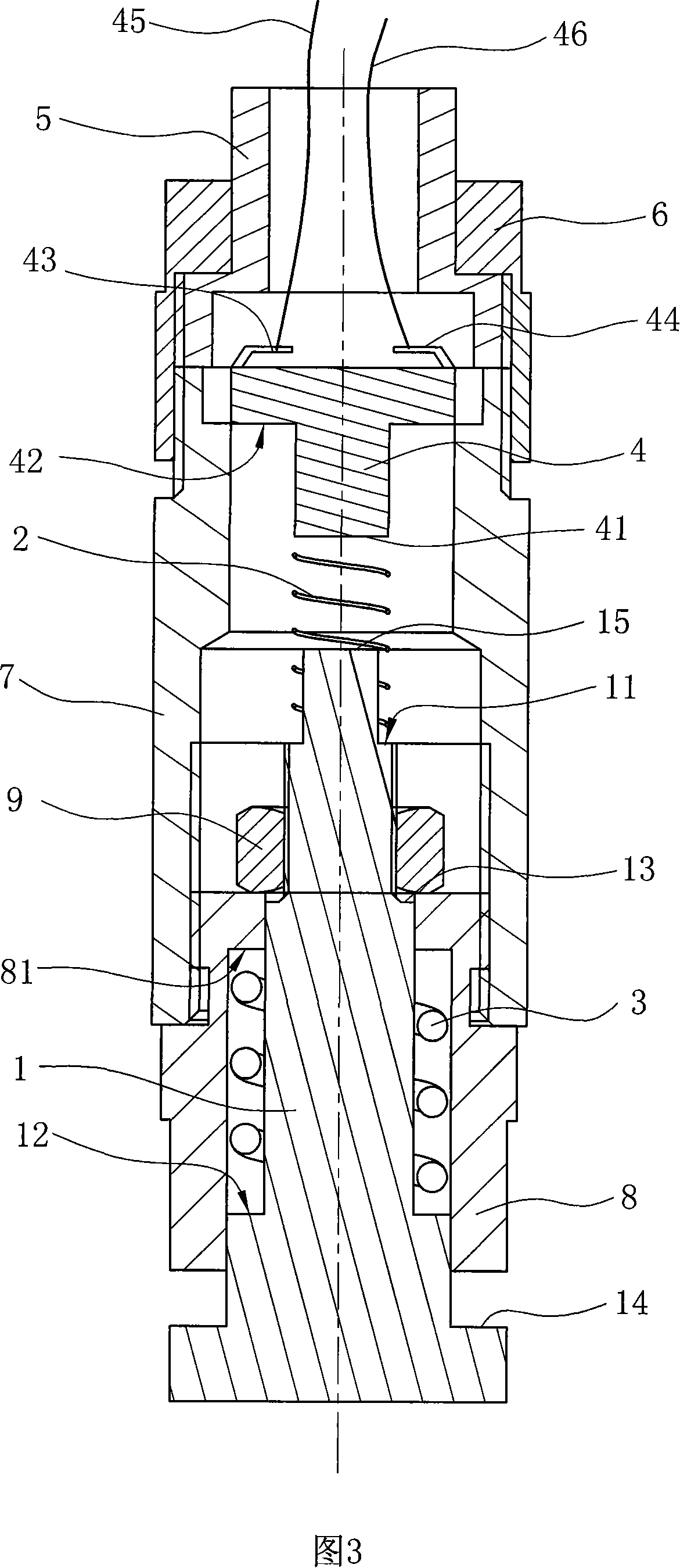
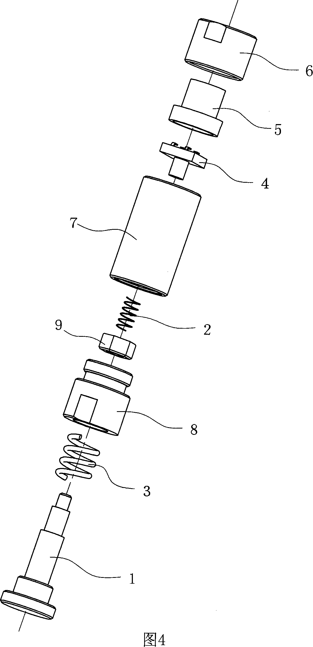
[0033] 1 to 8 are a preferred embodiment of the force sensing switch of the present invention, which includes a force transmission device composed of a first spring 2, a second spring 3 and a stepped shaft 1 with a second switch contact 15, Used to transmit external force; a contact switch 4 with a first switch contact 41 capable of inductively changing external force and lugs 43, 44; To fix and package the force transmission device and the contact switch 4.

[0034] Wherein, the stepped shaft 1 is installed in the bushing 8 and the shaft barrel 7, and can slide along the axial direction of the bushing 8 and the shaft barrel 7. The stepped shaft 1 has a first stepped surface 11 and a second stepped surface 12. , the third stepped surface 13 and the fourth stepped surface 14, the fourth stepped surface 14 is used as the bottom of the stepped s...


PUM


Abstract

The invention relates to a stress sensing switch, comprising a stress transmission device, a contact switch and a housing device, wherein, the stress transmission device comprises a first spring, a second spring and a step shaft provided with a second switch contact; the housing device comprises a shaft sleeve provided with an internal shoulder and a shaft tube connected with the shaft sleeve through one end; the step shaft is inserted into the shaft sleeve and the shaft tube; the first spring is sheathed between a first step face and a second step face of the step shaft; one end of the first spring is pressed against the internal shoulder of the shaft sleeve, while the other end of the first spring is pressed against the first step face; the contact switch is arranged inside the shaft sleeve fixedly and is provided with a stopper; one end of the second spring is pressed against the stopping face of the stopper, while the other end of the second spring is pressed against the second step face; the step shaft is also provided with a stopping block which is pressed against the upper end face of the shaft sleeve. Compared with the prior art, the sensing switch of the invention has a more compact structure an smaller volume, can detect and control the size of the external force, and can restore when on force is applied, thereby improving the reliability of the sensing of the external force.

Description

technical field [0001] The invention relates to a switch control device for sensing force, and the application of the force sensing switch in the technical field of automatic positioning and imaging. Background technique [0002] The common power switch generally adopts common push type and pull-on type. When using it, it needs to be manually connected to the power supply, which brings some inconvenience to many occasions where the switch is controlled to open and close according to external force conditions. [0003] For this reason, people have designed a force-sensing switch, which combines the external force with the closing and opening action of the switch, and can conveniently realize the purpose of automatically turning on the power according to the force situation without manual operation. [0004] As the application number is 88212154.5 (announcement number is CN2034737U) Chinese utility model patent "submersible hydraulic pressure sensor switch" just discloses a ki...

Claims


Application Information

Patent Timeline
Patent Type & Authority Applications(China)
IPC IPC(8): H01H35/02H01H35/00H01H3/38
Inventor 林强严正华史雪峰
Owner NINGBO HAISHU SIFANG ELECTRONICS
Learn More