Succus conducting device and conducting method thereof

A drainage device and body fluid technology, applied in the direction of wound drainage devices, suction devices, etc., can solve the problems of patient pain, inconvenient use, and low measurement accuracy in the storage area, so as to avoid pipeline connection, save the number of parts, and improve the overall compact effect

Inactive Publication Date: 2008-04-02
潘飞
View PDF0 Cites 0 Cited by
  • Summary
  • Abstract
  • Description
  • Claims
  • Application Information

AI Technical Summary

Problems solved by technology

Therefore, when the body fluid is drawn out from the thoracic or pericardial cavity and enters the micrometering area first, the medical personnel can more accurately estimate the drainage speed of the body fluid per unit time, and when the total amount of drainage fluid exceeds the total design capacity of the micrometering area, If the micrometering area is not cleared, the continuously increasing drainage fluid will naturally flow into the storage area. Due to the low measurement accuracy of the storage area, it will be difficult for medical staff to accurately estimate the hourly drainage volume, which will adversely affect treatment decisions.
On the other hand, since both the micro metering area and the storage area only have volume scales but lack time scales, in order to know the drainage volume of a certain unit time period in the future, it is often necessary to mark the drainage device and record several times continuously. After a period of time, many marking lines may be drawn on the drainage device, which makes the drainage device unattractive. When you want to use it again, you need to wipe off the original marking lines, which is inconvenient to use. Therefore, the existing drainage device has Lack of clarity and intuition
[0005] In addition, the existing traditional body fluid drainage device cannot provide a relatively stable safe negative pressure of -20cm to -25cm water column through the internal pressure attenuation design. Excessive negative pressure may cause pain and bleeding in patients, while too low Negative pressure is difficult to effectively drain the drainage to the patient's body
This is because the structural design of traditional drainage devices often uses multiple separate reservoirs, and the reservoirs are connected by independent plastic pipes or pipes made of other materials. On the one hand, this design will lead to the above-mentioned negative pressure force It cannot be transmitted effectively, on the other hand, it is easy to increase the chance of contamination during installation, and the more serious consequence is that it may lead to the occurrence of pneumothorax
[0006] In addition, the water used in the water seal part of the traditional drainage device is often not dyed, and there is no clear boundary between the colorless water and the container, which increases the difficulty of the work of the medical staff.

Method used


Image

  • Succus conducting device and conducting method thereof
  • Succus conducting device and conducting method thereof

Examples


Embodiment Construction

[0036] Reference will now be made in detail to the preferred embodiments of the invention, examples of which are illustrated in the accompanying drawings. Wherever possible, the same numbers will be used throughout the drawings to refer to the same or like parts. In addition, although the terms used in the present invention are selected from well-known and commonly used terms, some terms mentioned in the description of the present invention may be selected by the applicant according to his or her judgment, and the detailed meanings thereof are set forth herein described in the relevant section of the description. Furthermore, it is required that the present invention be understood not only by the actual terms used, but also by the meaning implied by each term.

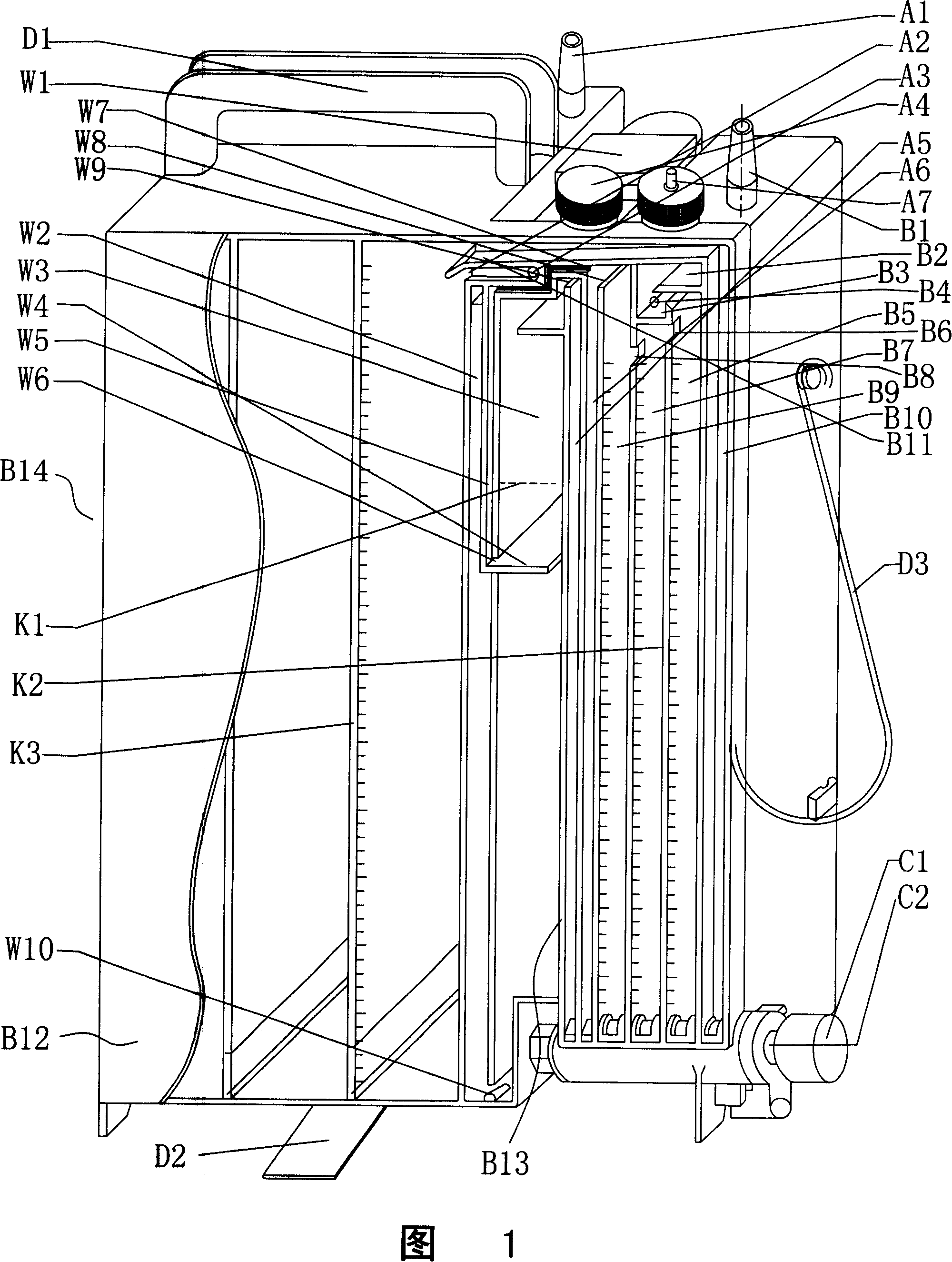
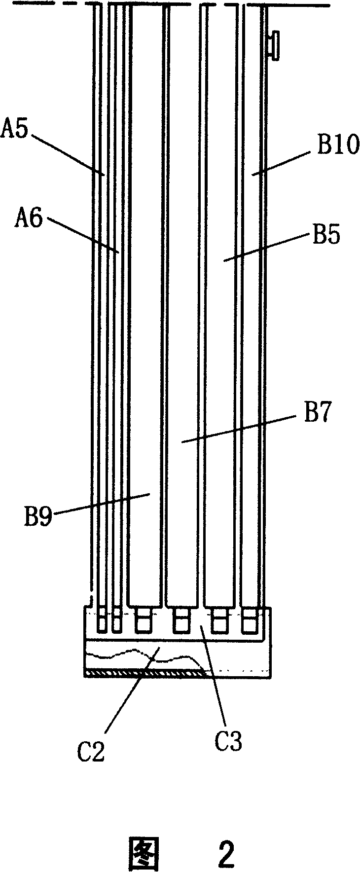
[0037] The body fluid drainage device of the present invention is roughly the same as the general traditional drainage device in terms of physical storage structure, and also separates two areas, namely the micro mete...


PUM


Abstract

The invention is to design a body fluid flow diverter and a flow diverting method for the flow diverter. The flow diverter consists of a storage area capable of storing body fluid and a non-storage area, a body fluid flow diverting interface, control valve assembly components, a pressure regulating valve and other parts, wherein, the non-store area comprises micro-metering area and water seal stabilizing area assembly components, suction channel assembly components and body fluid diverting channel assembly components, etc. The body fluid flow diverting method of the invention is that first the body fluid is diverted into a micro-metering area; when the diverted body fluid reaches the upper limit of the volume of the micro-metering area or the medical staff think the body fluid needs to be diverted, the body fluid in the micro-metering area is immediately diverted into a storage area, so as to empty the body fluid in the micro-metering area; and then the body fluid continues to be diverted into the micro-metering area, which can help the medical staff to repeatedly make use of the high-precision characteristic of the micro-metering area to estimate the body fluid diverted within unit time, so as to precisely measure the body fluid diverted within a time period and reduce estimation error.

Description

technical field [0001] The invention relates to a medical device, in particular to a body fluid drainage device and a drainage method thereof. Background technique [0002] After chest trauma, thoracic surgery and cardiac surgery, in order to observe the gas and fluid in the thoracic or pericardial cavity, including blood, lymph, etc., it is necessary to insert a drainage tube into the thoracic cavity or pericardial cavity to drain the gas and fluid that may threaten the life of the patient. Fluid is drained out of the body. [0003] The hourly drainage volume (that is, the total amount of fluid drained from the thoracic or pericardial cavity within a unit of time) is crucial after surgery or early after drainage tube placement. Combined with a variety of laboratory tests, and through the evaluation of the hourly drainage volume, the rate of bleeding in the chest cavity or pericardium can be determined, and then it can be determined whether it is necessary to re-open the ch...

Claims


Application Information

Patent Timeline
Patent Type & Authority Applications(China)
IPC IPC(8): A61M1/00A61M27/00
Inventor 周穗涛
Owner 潘飞
Why Eureka
Try Eureka