
Controllable gain general frequency converter for multiplication digital/analog converter

A technology of digital-to-analog converters and analog-to-digital converters, applied in modulation transfer, electrical components, transmission systems, etc., can solve problems such as large hardware scale, large difference in received signal strength, and reduced system flexibility and applicability. Achieve the effect of reducing hardware scale, increasing flexibility and adaptability

Inactive Publication Date: 2008-03-26
HARBIN ENG UNIV
View PDF0 Cites 3 Cited by
  • Summary
  • Abstract
  • Description
  • Claims
  • Application Information

AI Technical Summary

Problems solved by technology

In addition, due to the different influences of the environment, channel and target characteristics, the strength of the received signal of the system varies greatly. In order to make the system have the same adaptability to different signals, the receiver must have certain amplification and filtering functions. Certain gain control capability
[0003] The traditional frequency conversion and gain control are usually two independent circuit modules, that is, the signal is amplified or reduced to a certain range by the gain control circuit and then the frequency conversion operation is performed by the frequency conversion circuit. Therefore, the hardware scale of the system is generally large, and the parameters are determined. Generally, the frequency conversion circuit can only achieve one fundamental frequency, which reduces the flexibility and applicability of the system

Method used


Image

  • Controllable gain general frequency converter for multiplication digital/analog converter
  • Controllable gain general frequency converter for multiplication digital/analog converter
  • Controllable gain general frequency converter for multiplication digital/analog converter

Examples


Embodiment Construction

[0020] The present invention is described in more detail below in conjunction with accompanying drawing example:

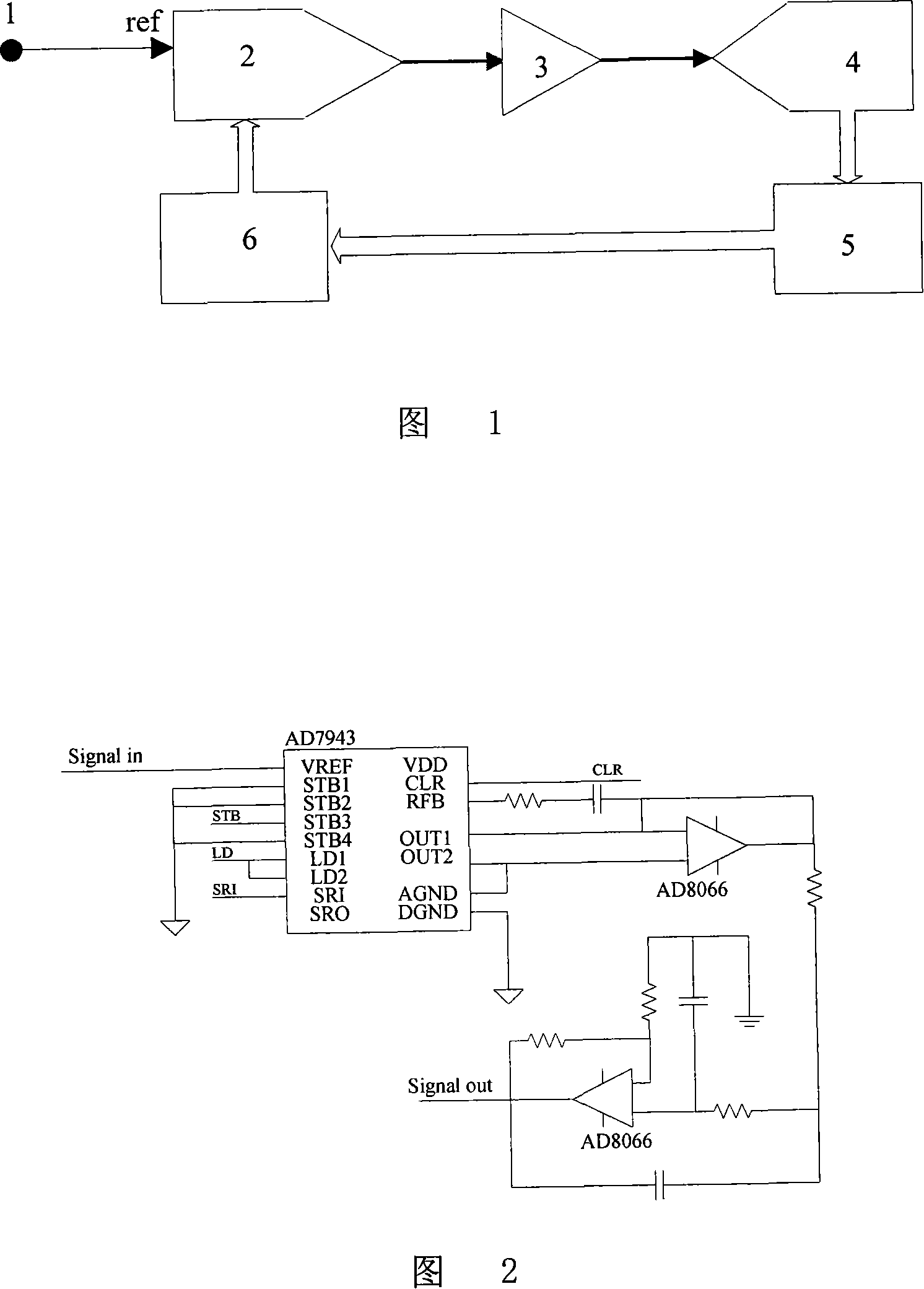
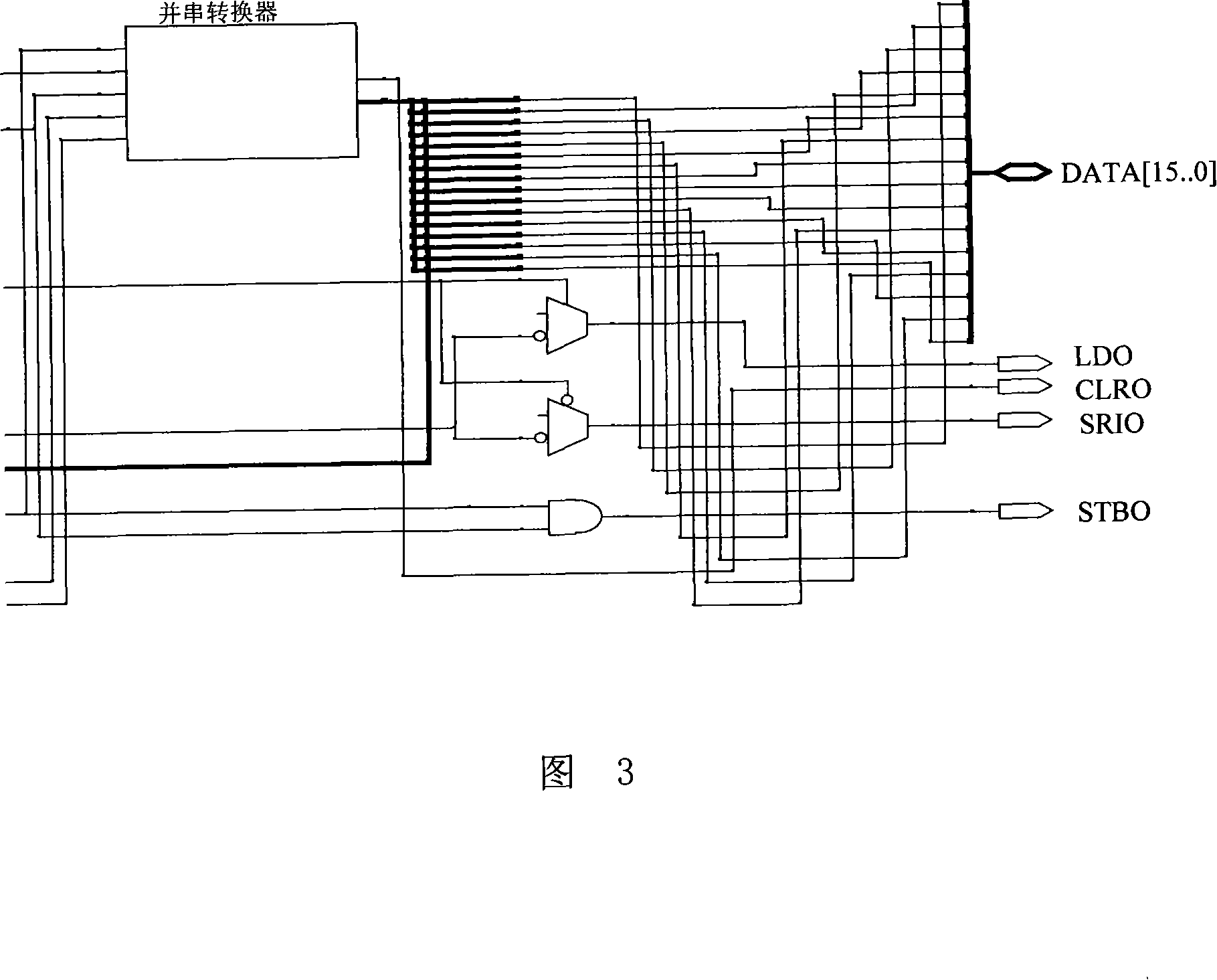
[0021] In conjunction with Fig. 1, the composition of the controllable gain general-purpose inverter based on the multiplying digital-to-analog converter includes the multiplying digital-to-analog converter 2, the base frequency and gain code generation circuit 6, the frequency selection circuit 3, the analog-to-digital converter 4 and the signal Processor 5, the signal received by the receiver becomes a signal with a certain carrier frequency and envelope information after passing through the preamplification and filtering circuit 1, denoted as S R (t) Input from the voltage reference terminal of the multiplying digital-to-analog converter 2, and then pass through the frequency selection circuit 3 to obtain the required base frequency signal, the base frequency signal is input to the analog-to-digital converter 4 to collect, and after being processed by the signal...


PUM


Abstract

This invention provides a controllable gain transducer based on a multiplication D / A converter including multiplication D / A converter2, base frequency and gain code generating circuit 6, frequency-selective circuit 3, D / A converter 4 and signal processor 5, in which, a signal received by a receiver is changed to signal 1 with a carrier frequency and envolope information after pre-amplification and filter circuit, which is input from the voltage reference end of 2 and through frequyency-selective circuit 3 to get a necessary base frequency signal to be input into D / A converter 4 to be collected and processed by signal processor 5 to be input into the base frequency and gain code generation circuit, the output of which is input into the multiplication D / A comverter2, which combines traditional mutual independent frequency conversion and gain control circuit modules by the multiplication function of a multiplication D / A converter to increase flexibility and adaptive ability of the system.

Description

(1) Technical field [0001] The invention relates to a frequency conversion and gain control circuit, in particular to a frequency conversion and gain control circuit widely used in the fields of radar, sonar, communication and medical treatment. (2) Background technology [0002] In the fields of radar, sonar, communication and medical treatment, most systems need to convert the received signal with a higher carrier frequency into a signal with a lower carrier frequency through down conversion, and then perform sampling and subsequent processing , so the frequency conversion circuit is an indispensable part of many systems in the above fields. In addition, due to the different influences of the environment, channel and target characteristics, the strength of the received signal of the system varies greatly. In order to make the system have the same adaptability to different signals, the receiver must have certain amplification and filtering functions. Certain gain control c...

Claims


Application Information

Patent Timeline
Patent Type & Authority Applications(China)
IPC IPC(8): H03D7/00H04B1/12
Inventor 么彬李海森周天魏玉阔陈宝伟刘文政刘晓
Owner HARBIN ENG UNIV
Learn More