Synthesizing method for urea

A urea and synthesis tower technology is applied in the field of traditional urea synthesis systems to achieve uniform distribution of gas and liquid, avoid back mixing and avoid reversible reactions.

Active Publication Date: 2011-10-12
BEIJING HANGHUA ENERGY SAVING ENVIRONMENTAL PROTECTION TECH CO LTD
View PDF7 Cites 0 Cited by
  • Summary
  • Abstract
  • Description
  • Claims
  • Application Information

AI Technical Summary

Problems solved by technology

Thoroughly solve many problems that have plagued the efficiency of urea synthesis for a long time

Method used


Image

  • Synthesizing method for urea
  • Synthesizing method for urea
  • Synthesizing method for urea

Examples


Embodiment Construction

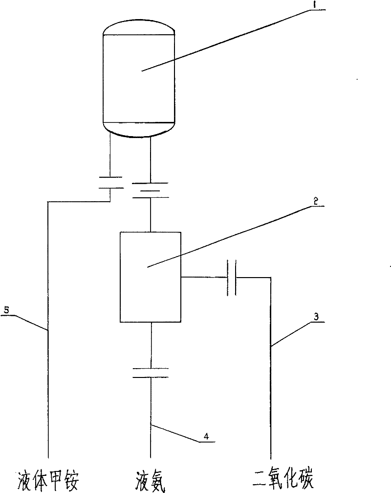
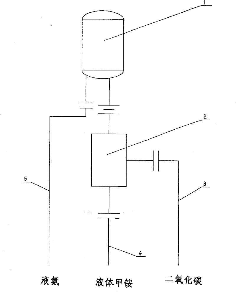
[0053] Depend on figure 1 , figure 2 , image 3 , Figure 4 , Figure 5 , Figure 6 , Figure 7 As shown, the high-pressure liquid-gas tube type rapid mixing reactor 2 is adopted to make the three materials entering the urea synthesis tower 1: liquid ammonia 3, gaseous carbon dioxide 4, liquid methylammonium 5 or any two of them become a completely uniform The liquid-gas mixture then enters the synthesis tower. The high-pressure liquid-gas tube type rapid mixing reactor 2 can atomize liquid ammonia and liquid methylammonium separately or simultaneously into 100-250 μm mist droplets (instead of liquid droplets) and then mix them with gaseous carbon dioxide to form a uniform two-phase flow. Solve the liquid-gas mixing problem that enters synthetic tower effectively, thereby realize each effect of the present invention.

[0054] The high-pressure liquid-gas tubular fast mixing reactor 2 is connected to the synthesis tower 1 through flange 21, flange 11, and high-pressure ...


PUM


Abstract

The present invention provides one new urea synthesizing process. One high pressure tubular quick liquid-gas mixing reactor is set in the material inlet of urea synthesizing tower, liquid ammonia and liquid methyl amine are atomized to form 100-250 micron fog drops, and the fog drops are mixed with gaseous CO2 to form homogeneous two-phase flow into the urea synthesizing tower, where methyl amineis dewatered to produce urea. The improved urea synthesizing process has no back mixing of materials, short reaction period, high synthesis efficiency, raised CO2 converting rate, saving in energy, high yield and other advantages.

Description

technical field [0001] The invention relates to a method for synthesizing urea, in particular to an improved method for a traditional urea synthesis system. Background technique [0002] The synthesis reaction of urea is divided into two steps: first, the synthesis reaction of liquid ammonia and gaseous carbon dioxide generates liquid ammonium carbamate (generally referred to as methyl ammonium), and its reaction formula is: [0003] 2NH 3 (liquid)+CO 2 (gas) = ​​NH 4 COONH 2 (liquid) [0004] Followed by the dehydration of ammonium carbamate to generate water and urea, the reaction formula is: [0005] NH 4 COONH 2 (Liquid)=CO(NH 2 ) 2 (liquid)+H 2 O (liquid) [0006] As we all know, the first step of the synthesis reaction is easy to complete, and the reaction conditions are relatively undemanding, while the second step of the dehydration reaction must be completed in a high-pressure synthesis tower, and sufficient residence time is required to ensure it. In th...

Claims


Application Information

Patent Timeline
Patent Type & Authority Patents(China)
IPC IPC(8): C07C273/04C07C273/02
CPCY02P20/50
Inventor 刘孝弟王军王文善李兵科崔晓兰
Owner BEIJING HANGHUA ENERGY SAVING ENVIRONMENTAL PROTECTION TECH CO LTD
Why Eureka
Try Eureka