Shower head

A nozzle and rotating wheel technology, applied in the direction of spraying device, spraying device, etc., can solve the problem that the nozzle cannot be converted, and achieve the effect of simple installation and connection

Inactive Publication Date: 2008-03-05
WEIDMANN PLASTICS TECH
View PDF6 Cites 1 Cited by
  • Summary
  • Abstract
  • Description
  • Claims
  • Application Information

AI Technical Summary

Problems solved by technology

But this sprinkler head cannot switch between the two spraying modes

Method used


Image

  • Shower head
  • Shower head
  • Shower head

Examples


Embodiment Construction

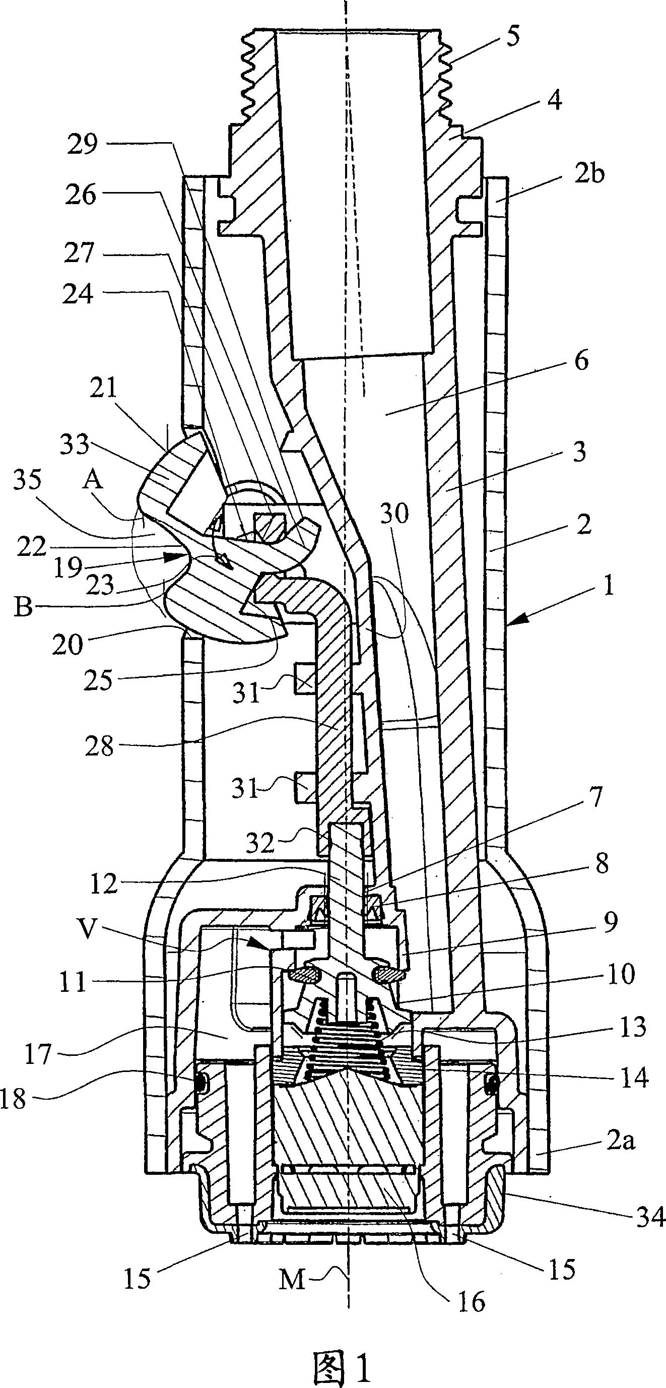
[0029] The spray head 1 shown in FIG. 1 has a substantially cylindrical housing 2 in which a water delivery pipe 3 is mounted. On the edge protruding from the housing 2, the water supply pipe 3 has a connecting pipe 4 with a connecting thread 5, at which connecting pipe the spray head 1 is connected to a hose (not shown here). The hose is preferably pulled out in a pipe bend, not shown here. The spray head 1 can then be pulled out, for example, downwards and used in particular as a dishwashing spray head.

[0030] At the other end of the water supply pipe 3 there is a known insert 34 which is sealed relative to the water supply pipe 3 with a sealing ring 18 and which has a water outlet 15 for spraying water and a flow former 16 in the center. The water flow is formed through the water outlet 15 or through the water flow former 16 . Thus two currents can be formed here. Suitable inserts 34 are known to those skilled in the art and therefore need not be described in detail he...


PUM


Abstract

The invention relates to a shower head which comprises a housing (2) wherein a valve (V), which comprises a closing body (10) which can be adjusted between two closing positions by changing the type of jet by means of an actuation device (19), is arranged. The actuation device (19) comprises a rotating wheel (33, 41, 51, 61, 71) which is arranged on the outer side of the housing (2), said rotating wheel being actively connected to the closing body (10) such that it can manually rotate in a limited manner in order to adjust the closing body (10). A valve pipe (3) is arranged in the housing (2), whereon the rotating wheel (33, 41, 51, 61, 71) is mounted in a rotationally limited manner. Said shower head can be manually actuated in a simple manner and can consist of very few parts.

Description

technical field [0001] The invention relates to a spray head, which has a casing, and a valve is arranged in the casing, and the valve has a locking mechanism, and the mechanism is moved between two closed positions by an operating device to switch the water spraying mode. Background technique [0002] A spray head of this type is known, for example, from DE 19803554A. Such sprays are used in particular for pull-out sprays or dishwashing sprays. The spray head is attached to a hose which is guided movable within the pipe bend. The spray head can be pulled out from under the pipe elbow. This type of spray head is also known as a "pull down" spray head. The valve is a switching valve that can be switched by a lever, so that different water flows can be selectively formed. The lever is here arranged below the elastic diaphragm in such a way that it cannot be seen from the outside. Switching takes place in two different operating positions of the diaphragm that are spaced a...

Claims


Application Information

Patent Timeline
IPC IPC(8): B05B1/18B05B1/16
CPCB05B1/18B05B12/002B05B1/1618
Inventor 本亚明·霍德尔卢茨·阿尔特内德亨宁·克斯
Owner WEIDMANN PLASTICS TECH
Why Eureka
Try Eureka