Optical element and production device for producing same

A technology for manufacturing devices and optics, applied in the field of manufacturing devices for manufacturing optical elements, can solve the problems that are not suitable for large-scale production, long time (about several hours to tens of hours, etc.)

Inactive Publication Date: 2008-03-05
SONY CORP
View PDF1 Cites 12 Cited by
  • Summary
  • Abstract
  • Description
  • Claims
  • Application Information

AI Technical Summary

Problems solved by technology

However, in this casting method, it takes a long time (about several hours to several tens of hours) to sufficiently cure the resin, and therefore, it is not suitable for mass production

Method used


Image

  • Optical element and production device for producing same
  • Optical element and production device for producing same
  • Optical element and production device for producing same

Examples


Embodiment Construction

[0054] Embodiments of the present invention will be described in detail below with reference to the accompanying drawings.

[0055] For ease of understanding, various directional terms such as right, left, up, down, right side, etc. will be used in the following description. However, such terms should be understood with reference to the drawing or drawings on which the corresponding element or portion is shown.

[0056] Referring to FIGS. 1 to 8 , there is shown a manufacturing apparatus 1 according to a first embodiment of the present invention, which manufactures a lens as an optical element.

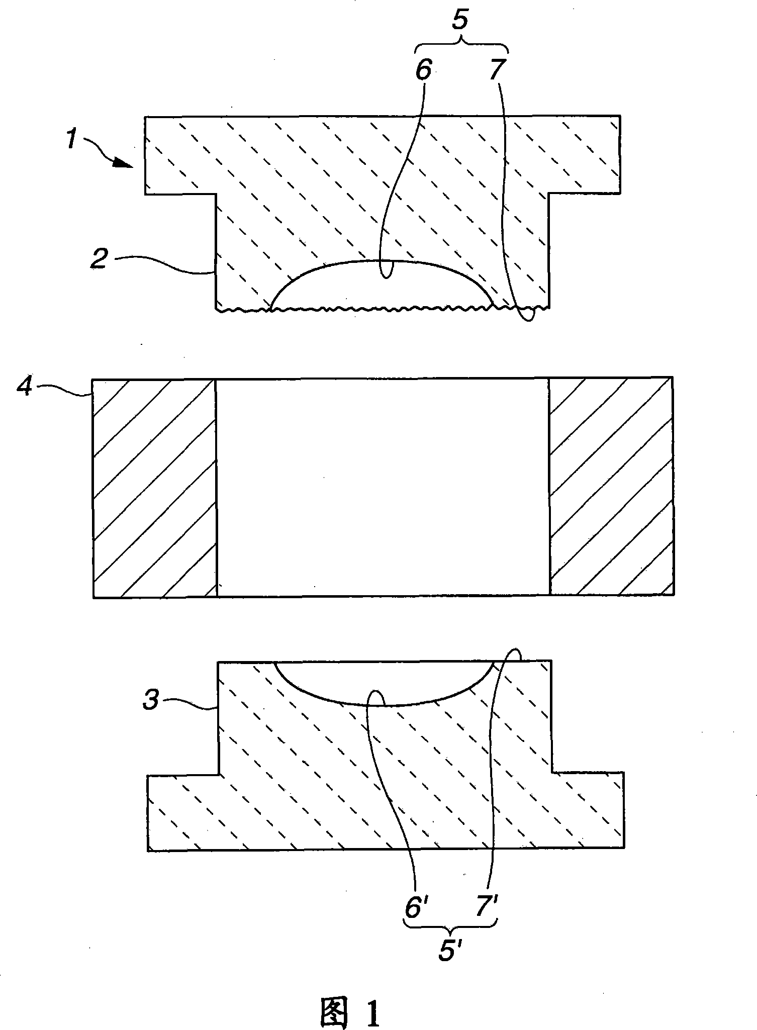
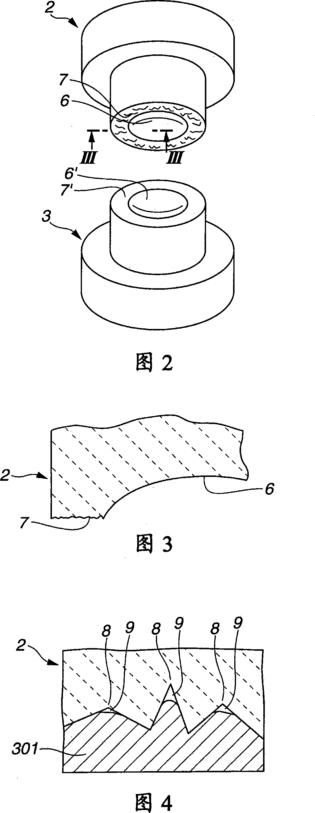
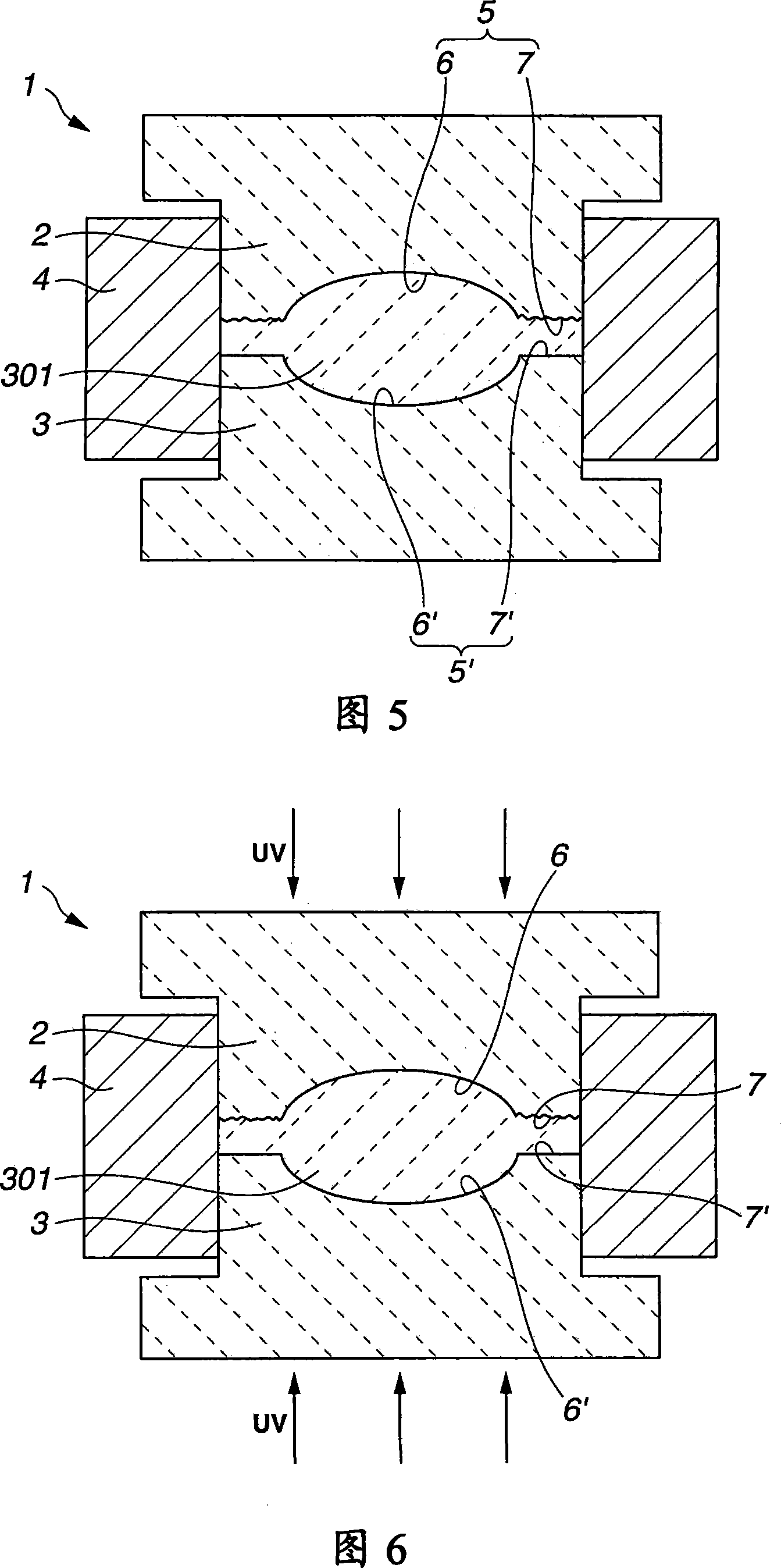
[0057] As shown in FIG. 1 , the manufacturing device 1 includes an upper glass mold 2 , a lower glass mold 3 and a centering sleeve 4 , wherein the upper glass mold 2 and the lower glass mold 3 are centered and positioned relative to each other by the centering sleeve 4 . The upper glass mold 2 and the lower glass mold 3 are made of a glass material exhibiting high transmittance to u...


PUM


Abstract

A lens (101) produced from a radial rays-curing material comprises a lens proper portion (102) that serves as an optically effective part of the lens (101), and a circular flange portion (103) that surrounds the lens proper portion (102) and serves as an optically non-effective part of the lens (101). The circular flange portion (103) has front and rear surfaces (103a, 103b) that are different in appearance.

Description

[0001] Cross References to Related Applications [0002] The present invention contains subject matter related to Japanese Patent Application JP2006-233727 filed in the Japan Patent Office on Aug. 30, 2006, the entire contents of which are hereby incorporated by reference. technical field [0003] The present invention relates to an optical element or lens using an ultraviolet-curable resin or the like as a material, and a manufacturing apparatus (production apparatus) for manufacturing the optical element. Background technique [0004] In optical elements (such as lenses, etc.) used in optical instruments such as cameras, etc., there are generally two types: one made of glass and the other made of resin. Compared with optical elements made of glass, optical elements made of resin are light in weight, excellent in impact resistance, and low in cost, and therefore, resin-based optical elements have recently been widely used in the field of optical instruments. [0005] For t...

Claims


Application Information

Patent Timeline
Patent Type & Authority Applications(China)
IPC IPC(8): G02B3/00B29C33/44B29C33/38B29C33/42B29C39/26
CPCC03B2215/68B29D11/00432C03B2215/72C03B11/08C03B2215/49G02B7/022B29D11/00413B29D11/00528B29D11/00
Inventor 辻巧石桥雄一郎
Owner SONY CORP
Why Eureka
Try Eureka