Twisting head rotor
A rotor and pivot pin technology, applied in textiles, papermaking, yarn, etc., can solve the problems of reducing the cost of removing and installing the roller frame, and achieve the effects of preventing insufficient lubricant, reducing costs, and reducing wear and tear.
Inactive Publication Date: 2011-01-05
ZHUOLANG INTELLIGENT MACHINERY CO LTD
View PDF2 Cites 0 Cited by
- Summary
- Abstract
- Description
- Claims
- Application Information
AI Technical Summary
Problems solved by technology
However, this solution has been found to be not very practical, as the cost of removing and installing the roll housing is only slightly lower than a complete roller bearing replacement (in the event of a lack of lubrication requiring replacement of the roller bearing)
Method used
View moreImage
Smart ImageViewing Examples
Examples
Embodiment Construction
Login to View More PUM
 Abstract
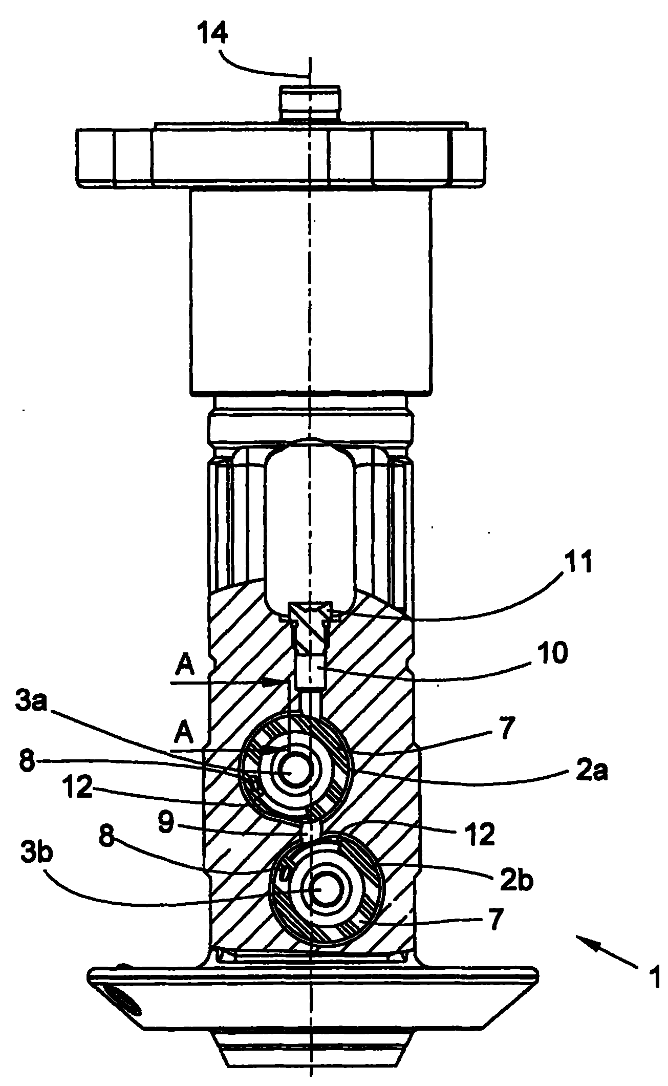
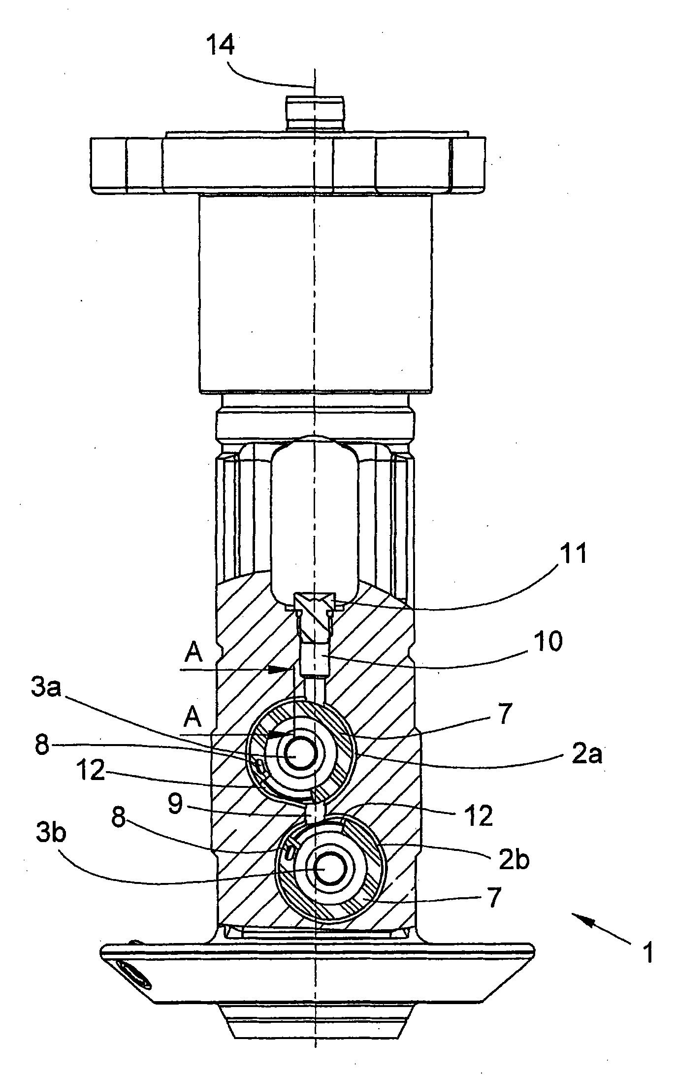
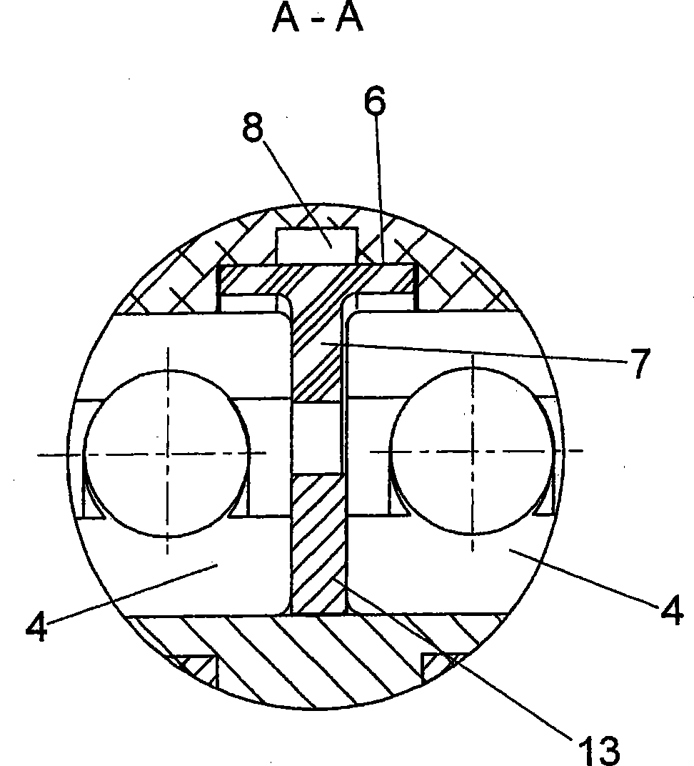
The invention provides a twisting head rotor (1) for the cabling machine. The twisting head rotor comprises two compensation rolls (5) arranged in pairs which are used for making line tension of two lines even, wherein, two pairs of compensation rolls can be arranged rotatablely on each pivoting pin (3a, 3b) in the twisting head rotor (1), the pivoting pins (3) are arranged in dead eyes (2a, 2b),two roller bearings (4) are located for mounting the pivoting pin (3a, 3b), the roller bearing pair is separated with each other by an isolating device (7), one of the two dead eyes (2a, 2b) is connected to a connecting device (11) for supplying lubricant, two dead eyes are connected with each other through a through hole (9).
Description
twist head rotor technical field The invention relates to a twisting head rotor for a rope winding machine. Background technique In the rope winding machine, the first wire is drawn from a first stationary supply cylinder arranged above the hollow spindle, while the second wire drawn from the second supply cylinder is centrally introduced into the hollow spindle from below. The second wire leaves the hollow spindle laterally and rotates around the first supply drum into a wire balloon before being taken away together with the first wire by a twisting head rotor mounted freely rotatable above said hollow spindle. The twist head rotor has two pairs of compensating rollers which are respectively arranged on a common pivot pin. The two pivot pins are arranged in bearing bores extending transversely to the longitudinal axis of the twist head rotor arranged parallel to each other. The two pivot pins are mounted respectively in two roller bearings arranged side by side in the b...
Claims
Login to View More Application Information
Patent Timeline
 Patent Type & Authority Patents(China)
IPC IPC(8): D01H13/00
CPCD01H7/02D01H7/20D02G3/285
Inventor 克里斯蒂安·费尔伯迪特尔·莱坞托尔德沃尔夫冈·舍夫勒伯恩哈德·沃尔尼
Owner ZHUOLANG INTELLIGENT MACHINERY CO LTD
Features
- Generate Ideas
- Intellectual Property
- Life Sciences
- Materials
- Tech Scout
- Unparalleled Data Quality
- Higher Quality Content
- 60% Fewer Hallucinations
Learn More Browse by: Latest US Patents, China's latest patents, Technical Efficacy Thesaurus, Application Domain, Technology Topic, Popular Technical Reports.
© 2025 PatSnap. All rights reserved.Legal|Privacy policy|Modern Slavery Act Transparency Statement|Sitemap|About US| Contact US: help@patsnap.com


