
Disk chipper

A disc chipper and cutter head technology, which is used in the manufacture of veneer chips, wood processing appliances, manufacturing tools, etc., can solve the problems of inability to adjust the distance and narrow cutting range, and achieve a wide cutting range and many cutting specifications. Effect

Inactive Publication Date: 2008-03-05
江苏保龙机电制造有限公司
View PDF0 Cites 14 Cited by
  • Summary
  • Abstract
  • Description
  • Claims
  • Application Information

AI Technical Summary

Problems solved by technology

The disadvantage of this kind of disc chipper is that the surface of the cutter head is a spiral surface, and the distance from the edge of the flying knife set on the cutter head to the surface of the cutter head cannot be adjusted, so only one specification of wood chips can be cut. That is, the length of cutting wood chips is fixed, and the cutting range is narrow

Method used


Image

  • Disk chipper
  • Disk chipper
  • Disk chipper

Examples


Embodiment Construction

[0017] The present invention will be described in further detail below in conjunction with the accompanying drawings and embodiments.

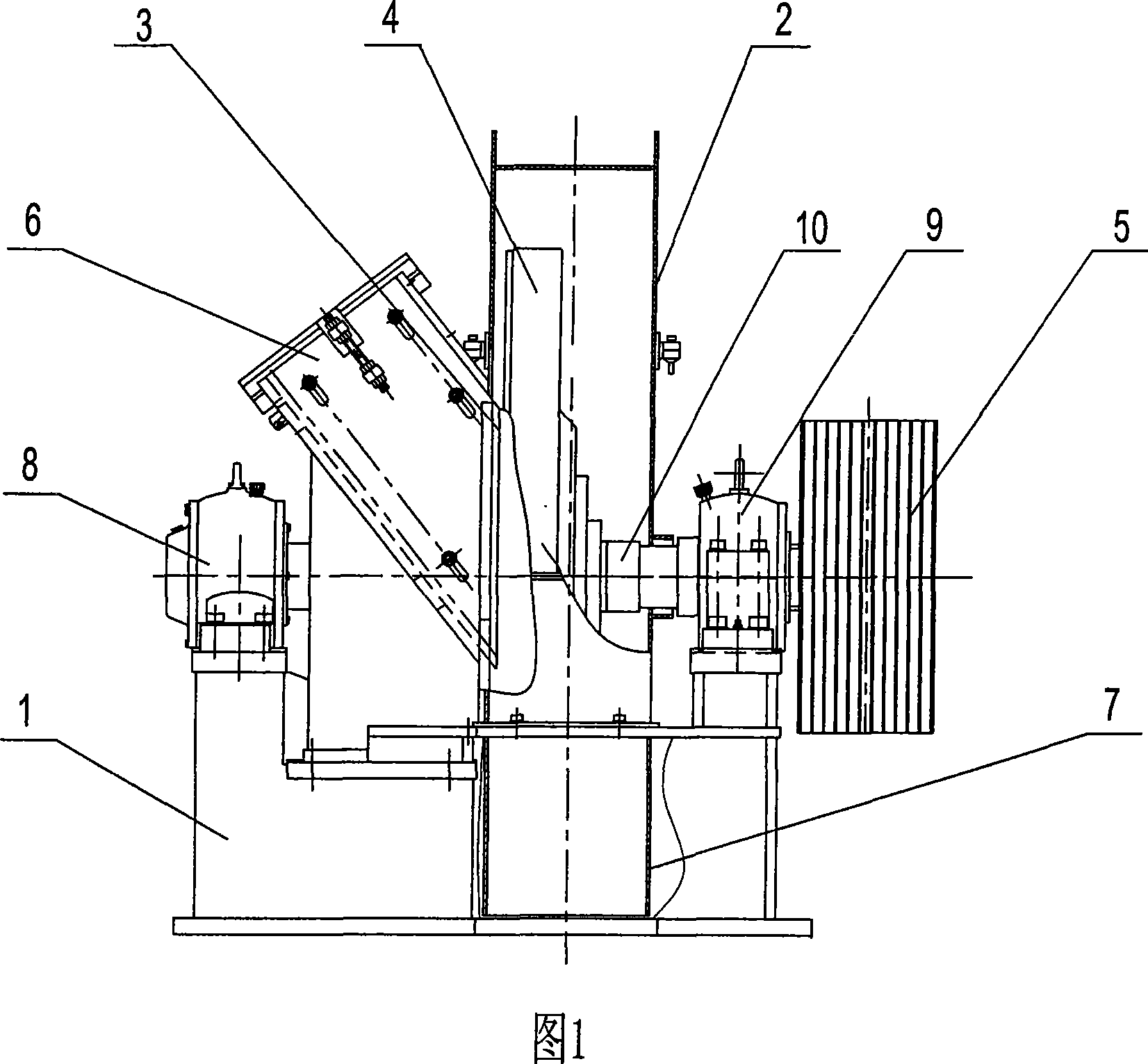
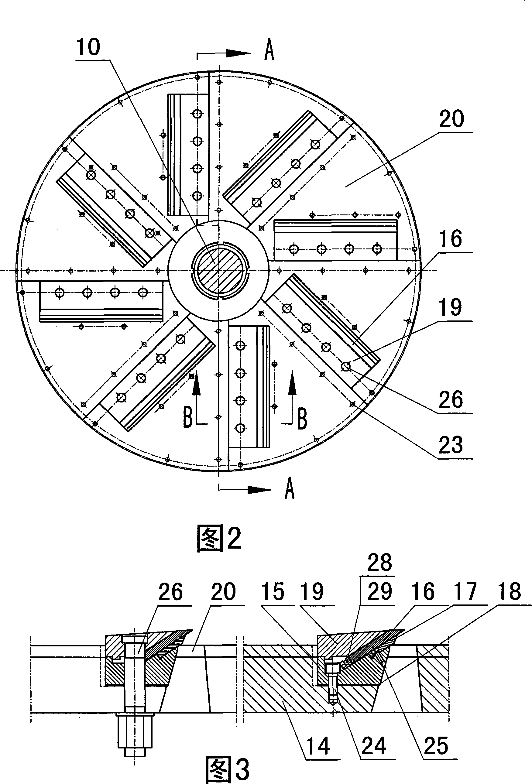
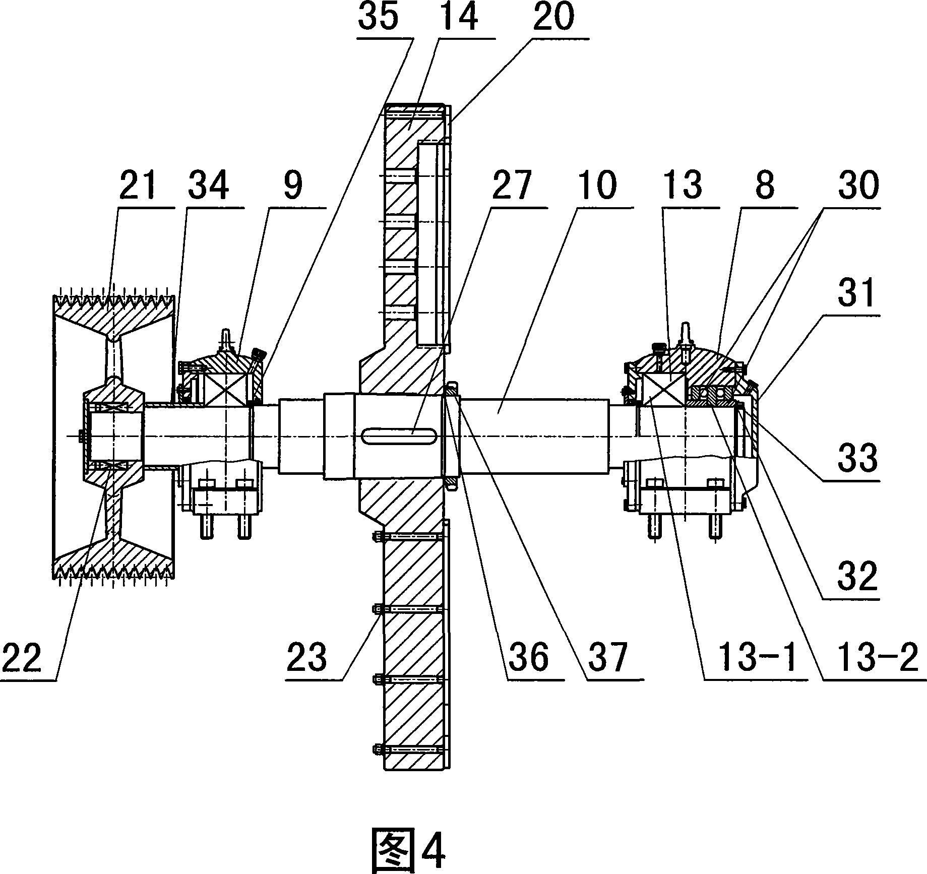
[0018] As shown in Figures 1 to 5, a disc chipper includes a machine base 1, a cutter head cover 2, a feeding device 3, a cutter head device 4, and a transmission device 5, and the cutter head cover 2 is fixed on the machine. On the seat 1, a feeding device 3 is fixed on the side of the cutter head cover 2, and a feeding port 6 is opened on the feeding device 3. The bottom knife 11, the side knife 12 on the left side and the side knife 12 on the right side are installed on the feeding device 3. The side knife 12, the lower part of the cutterhead cover 2 has a discharge port 7, and the cutterhead device 4 includes a main shaft 10, a cutterhead 14, 8 flying knives 16, 8 back knives 17, 8 pressure knife blocks 19, 8 Wear-resistant plate 20, described cutter head 14 disc surfaces are plane, wear-resistant plate 20 is fan-shaped, and 8 wear-resista...


PUM


Abstract

The present invention relates to chipping machine, and is especially one kind of disc type chipping machine, which includes one machine bed; one capstan housing on the machine bed; one feeding device on the capstan housing and with material inlet, bottom cutter, side cutter and discharge opening; one capstan device including spindle, capstan, flying cutter and cutter pushing block; and one driving device. The disc type chipping machine has the advantages of wide chipping range and capacity of chipping in different sizes.

Description

technical field [0001] The invention relates to chippers, in particular to a disc chipper. Background technique [0002] Disc chipper is a kind of cutting equipment widely used in fiberboard, pulp, paper mills and other manufacturing industries. It uses branches, slabs, logs, etc. The bottom knife and side knife in the feeding device cooperate to cut raw materials into wood chips of certain specifications. The surface of the cutter disc in the cutter disc device of the existing disc chipper is generally a helical surface, and a pressure block is arranged on the flying knife, and the lower part of the flying knife is arranged on the cutter disc. The disadvantage of this kind of disc chipper is: the surface of the cutter head is a spiral surface, and the distance from the edge of the flying knife set on the cutter head to the surface of the cutter head cannot be adjusted, so only one specification of wood chips can be cut. That is, the length of the cut wood chips is fixed, ...

Claims


Application Information

Patent Timeline
Patent Type & Authority Applications(China)
IPC IPC(8): B27L5/00
Inventor 周水保殷群赵志方
Owner 江苏保龙机电制造有限公司
Learn More