
Electronic navigation positioning shooting monitoring system

A monitoring system and electronic navigation technology, applied in closed-circuit television systems and other directions, can solve the problems of hidden dangers in security protection, inability to obtain, and limited field of view angle for recording, so as to improve the level and ability of security protection and the angle of field of view The effect of large scope and high level of technological innovation

Inactive Publication Date: 2008-02-20
TIANJIN YAAN TECH CO LTD
View PDF0 Cites 14 Cited by
  • Summary
  • Abstract
  • Description
  • Claims
  • Application Information

AI Technical Summary

Problems solved by technology

But there are still many shortcomings in the existing camera monitoring system: 1. the front-end equipment of the existing camera monitoring system is all made up of a single camera, and the operator can only obtain the scene picture information through a single camera, and the recorded images The field of view is limited, and it is impossible to record and monitor situations outside the range of the field of view
2. For some other monitoring systems with dynamic detection function, when the monitoring camera finds an abnormal situation, it can turn the body to follow the moving object and monitor it; but with the rotation of the body, its field of view angle also changes , the blind area of ​​surveillance is formed in the area outside the field of view, which lays hidden dangers for safety precautions
3. There are some security monitoring systems that will send out an alarm when a suspicious situation is captured, but the image cannot be enlarged in the area of ​​the suspicious situation, and the operator cannot get more image details in the image displayed by the monitoring system, so that they cannot Quickly and correctly make judgments, so that the security monitoring system cannot play its due role

Method used


Image

  • Electronic navigation positioning shooting monitoring system
  • Electronic navigation positioning shooting monitoring system
  • Electronic navigation positioning shooting monitoring system

Examples


Embodiment Construction

[0017] The present invention will be further described in detail below through the specific examples, the following examples are only descriptive, not restrictive, and cannot limit the protection scope of the present invention with this.

[0018] The cloud platform of the present invention can be panned, pitched and zoomed.

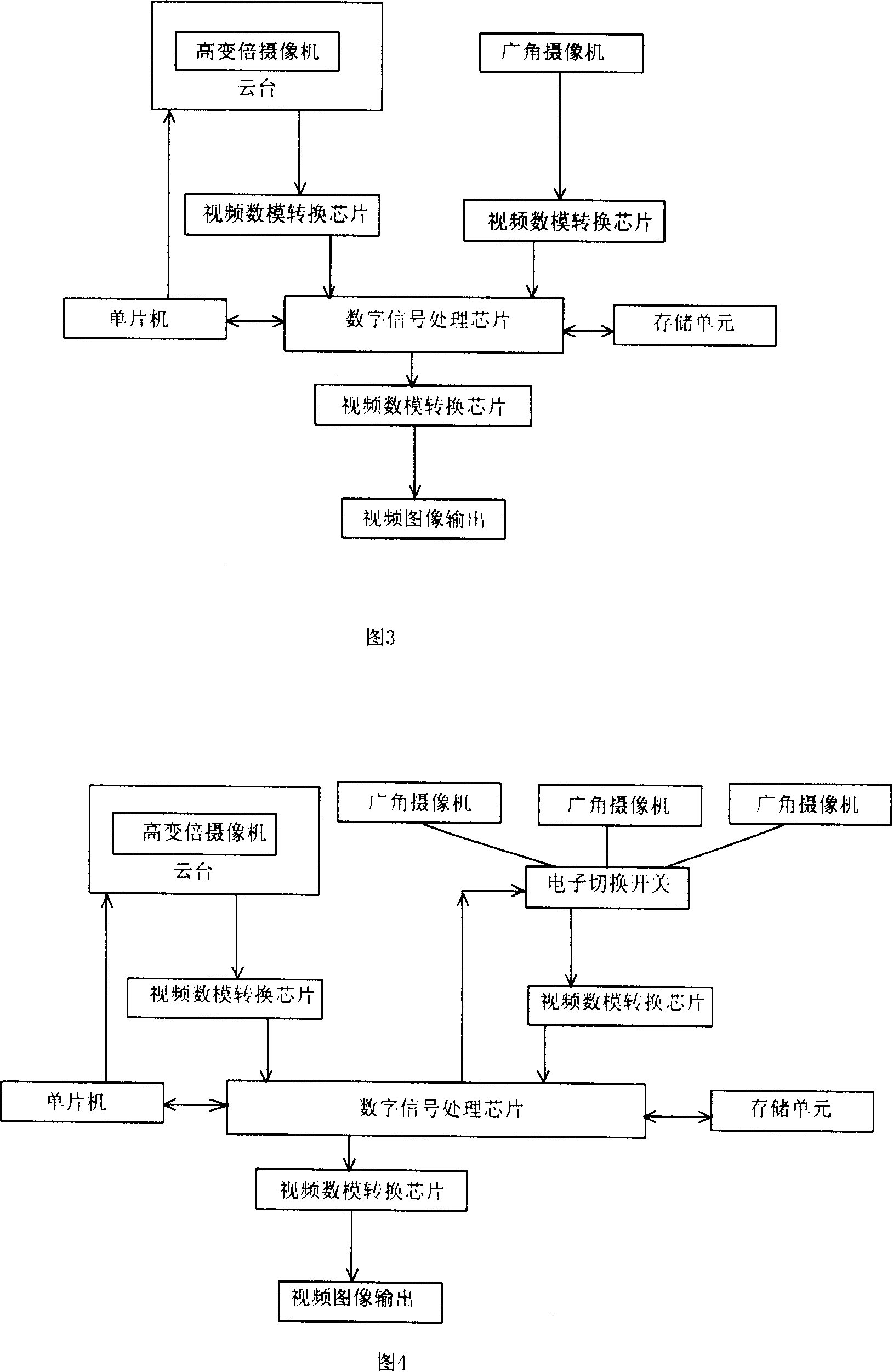
[0019] The wide-angle camera of the present invention: used for monitoring the whole area.

[0020] The high-zoom camera of the present invention: track and enlarge partial images.

[0021] The single-chip microcomputer of the present invention: manages, dispatches and processes data.

[0022] The video digital-to-analog conversion chip of the present invention: can convert between digital signals and analog signals

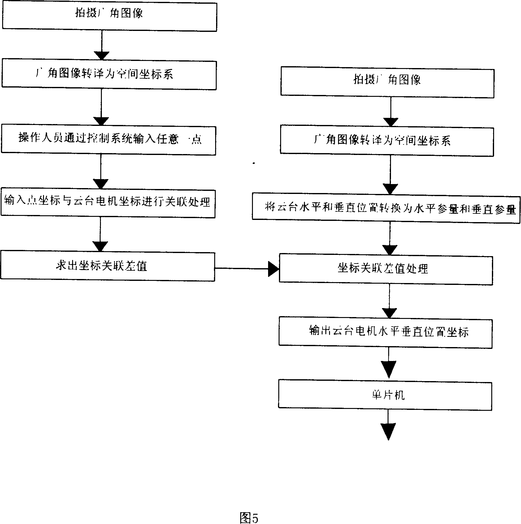
[0023] The digital signal processing chip of the present invention: corrects the distortion produced by the cameras, superimposes the videos produced by the two cameras, detects the image changes in the camera area, makes the two cameras p...


PUM


Abstract

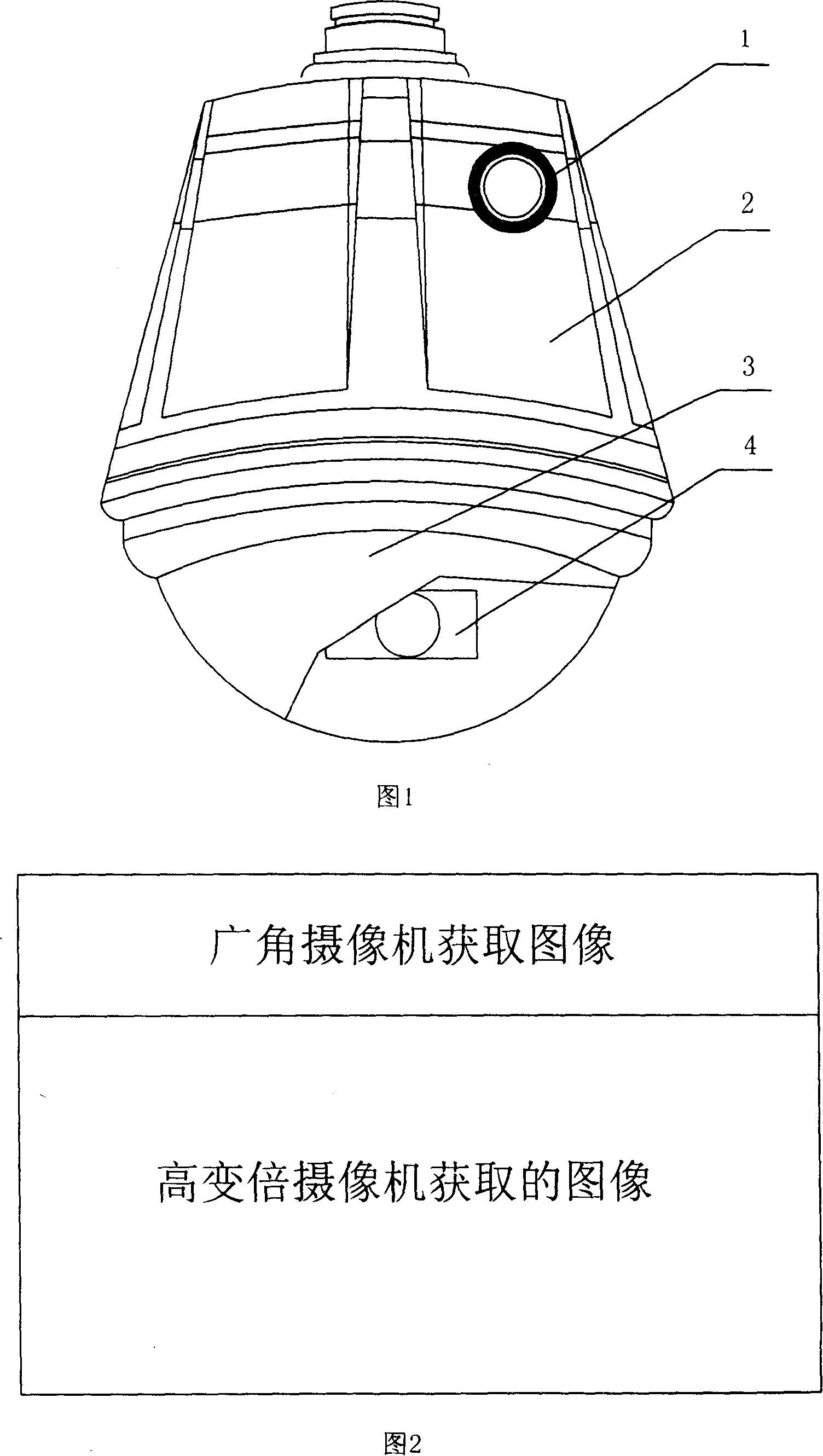
The utility model relates to an electronic navigation and positioning image monitoring system, which mainly comprises a pan-tilt head and a high-variable power video camera, wherein the high-variable power video camera is arranged in the spherical cover of the pan-tilt head, a wide-angle video camera is also arranged in a protective casing of the pan-tilt head; the control circuit in the pan-tilt head controls the linked movements between the video image of the wide-angle video camera and the video image of the high-variable power video camera. The utility model has the advantages of simple integral structure, reasonable design, wide angle of the monitoring area and tracing an optional area in the monitoring angle range and zooming out the image. The utility model is an image monitoring system with high technology innovation level and broad application range.

Description

technical field [0001] The invention belongs to the field of security monitoring, in particular to an electronic navigation positioning camera monitoring system. Background technique [0002] The camera monitoring system is an important part of the field of security monitoring. Through the video recording of the scene by the camera in the camera monitoring system, the operator can monitor the scene from the display device, so that the camera's field of view angle can be known even without on-site patrol. The situation at the scene. At present, camera monitoring systems are installed in many places, such as banks, stock exchanges, shopping malls, high-end office buildings and other places, which effectively improve the security and prevention capabilities. But there are still many shortcomings in the existing camera monitoring system: 1. the front-end equipment of the existing camera monitoring system is all made up of a single camera, and the operator can only obtain the sc...

Claims


Application Information

Patent Timeline
IPC IPC(8): H04N7/18
Inventor 贾云翔
Owner TIANJIN YAAN TECH CO LTD
Learn More