
Data forwarding method for layer 2 network and network and node devices

A technology of node equipment and forwarding method, which is applied in the direction of data exchange network, data exchange through path configuration, digital transmission system, etc., and can solve problems such as inability to realize connection, inability to plan in a unified way, inability to forward multiple nodes, etc.

Active Publication Date: 2008-02-20
HUAWEI TECH CO LTD
View PDF0 Cites 51 Cited by
  • Summary
  • Abstract
  • Description
  • Claims
  • Application Information

AI Technical Summary

Problems solved by technology

[0025] 1. The MAC address used in the existing technology is the globally unique MAC address of the device, which cannot be planned uniformly by the network manager, cannot aggregate MAC addresses, and cannot judge the location of the endpoint of the connection through the MAC address
[0026] 2. Since the length of MAC+VID is 60 Bits, theoretically the label combined with MAC+VID should be able to provide 2 60 label capacity, but the MAC address actually used is the MAC address of the device. The number of different ESPs arriving at a device is determined by the VID of the allocated PBT, and the length of the VID is 12 bits, so the maximum can only be 4096. There are great limitations
[0027] 3. In the prior art, an ESP is identified by the MAC address and VID of the destination device. The destination MAC is the global MAC of the device. When the message is forwarded by the intermediate node, it can only be forwarded to the destination node and cannot be forwarded to multiple nodes. , so the existing technology can only support point-to-point (P2P) connection, and cannot realize point-to-multipoint (P2MP) or multipoint-to-multipoint (MP2MP) connection
[0028] 4. The existing technology can only support unicast, not multicast or broadcast connections

Method used


Image

  • Data forwarding method for layer 2 network and network and node devices
  • Data forwarding method for layer 2 network and network and node devices
  • Data forwarding method for layer 2 network and network and node devices

Examples


Embodiment Construction

[0099] In order to make the object, technical solution and advantages of the present invention clearer, the present invention will be further described in detail below with reference to the accompanying drawings and examples.

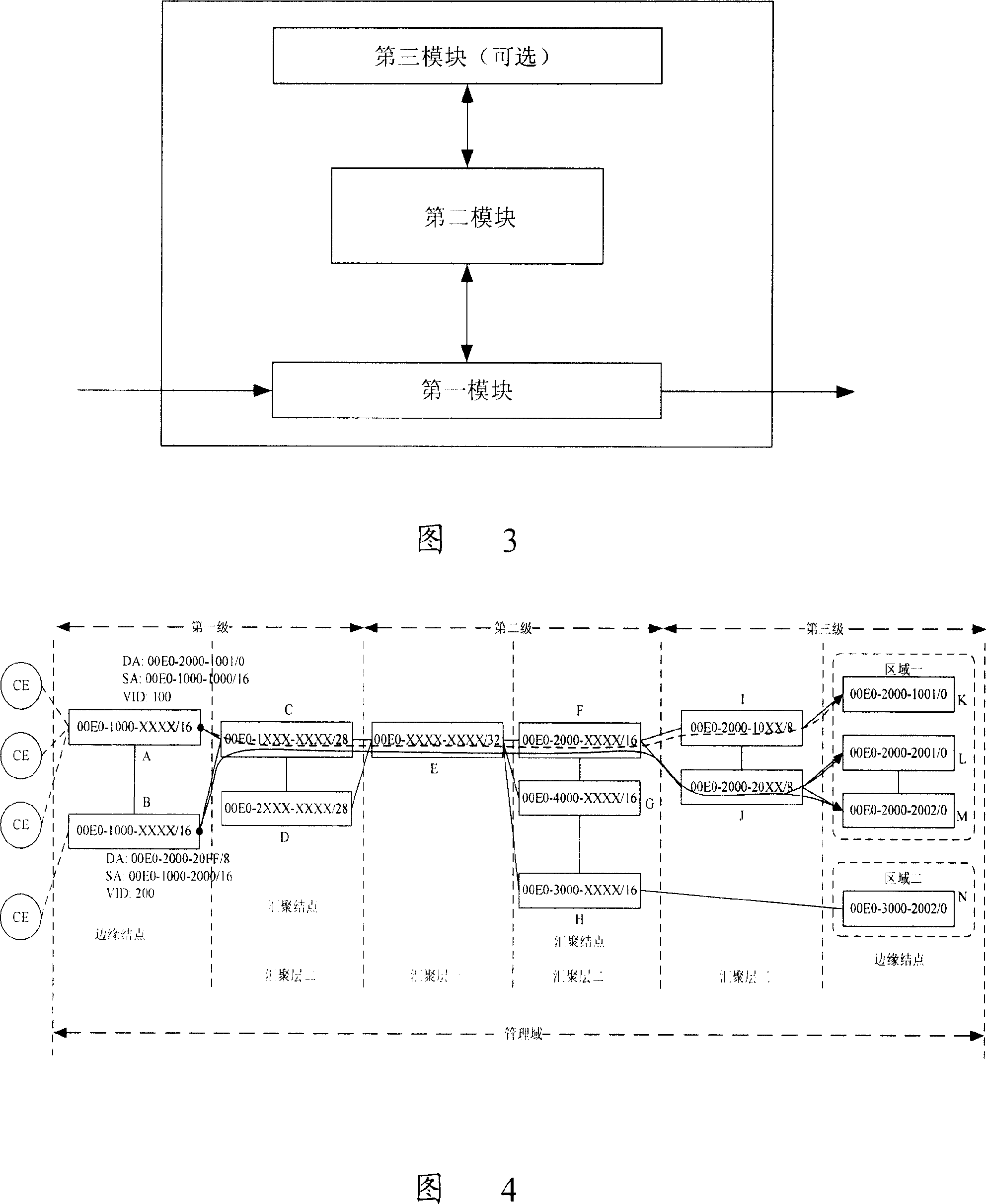
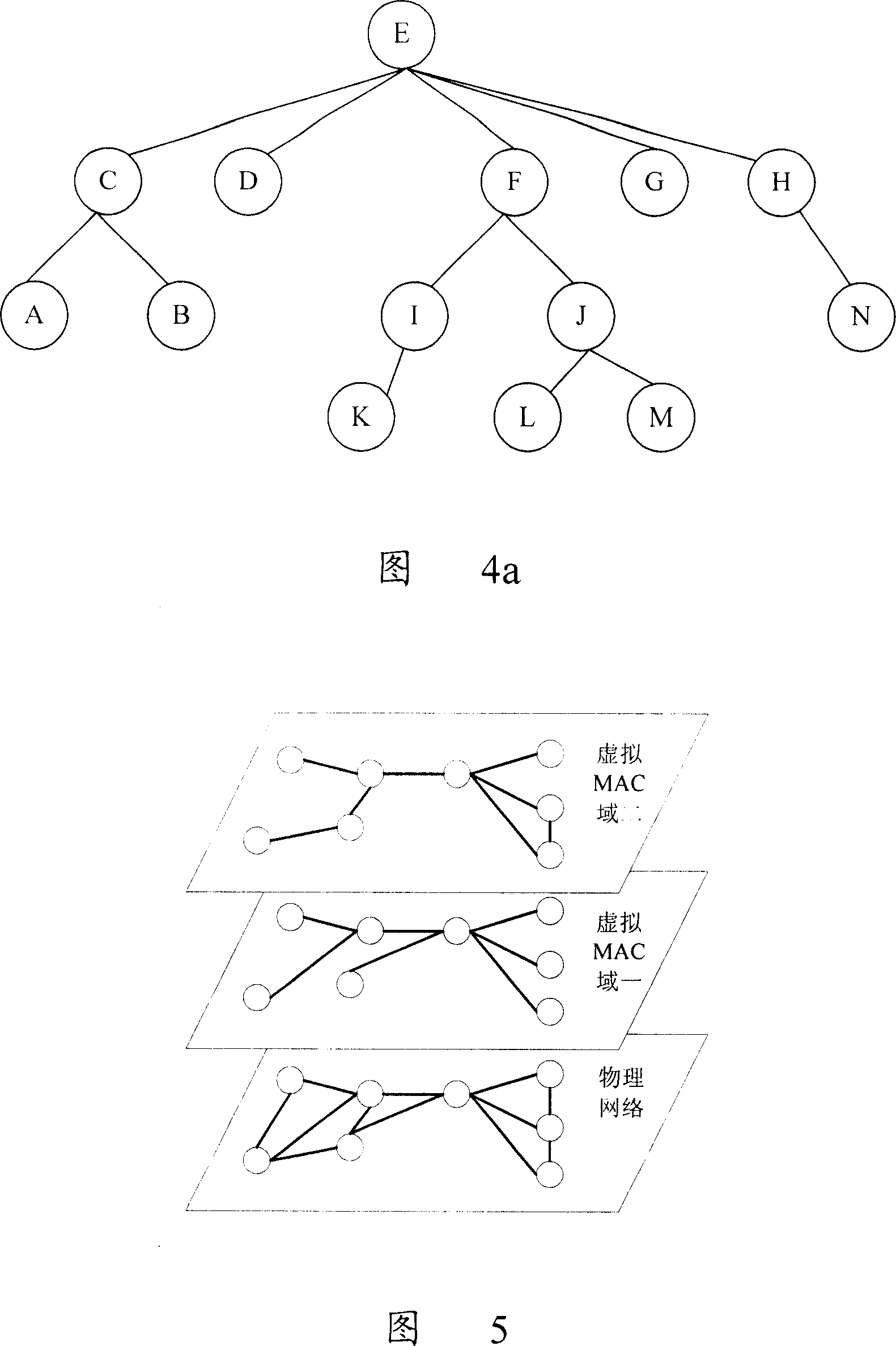
[0100] The main idea of ​​the data forwarding method, node device and network in the two-layer network provided by the present invention is: set up a management domain in the network, and uniformly configure virtual MAC addresses for the node devices in the management domain according to a predetermined convergence principle, Introduce identification information for the virtual MAC address to identify the virtual MAC address domain to which the node device belongs; when the network forwards data, the edge node device uses the virtual MAC address to encapsulate the received data, and according to the data configured with the virtual MAC address The forwarding channel forwards the data to the destination node device.

[0101] The present invention can be ...


PUM


Abstract

The utility model discloses a data rely method, a network and a node device in a two-layer network, which sets an management field in a network, and uniformly deploys virtual MAC addresses for the node devices in the management field according to a predetermined convergence principle, and imports identifying information used for marking the virtual MAC address field which the node device belongs to, for the virtual MAC address; when the network transmits data, a marginal node device encapsulates the received data with a virtual MAC address, and transmits the data to a destination node device according to a virtual MAC address forwarding table which is deployed with virtual MAC addresses. The utility model has the advantages that making the quantity of ESP reaching a destination device not be limited by the quantity of VID of the distributive PBT, extending the quantity of ESP reaching a destination device, truly realizing a tag capacity of 260 in a limited cyberspace, the connection of P2MP and MP2MP, and supporting a multicasting connection and a broadcasting connection.

Description

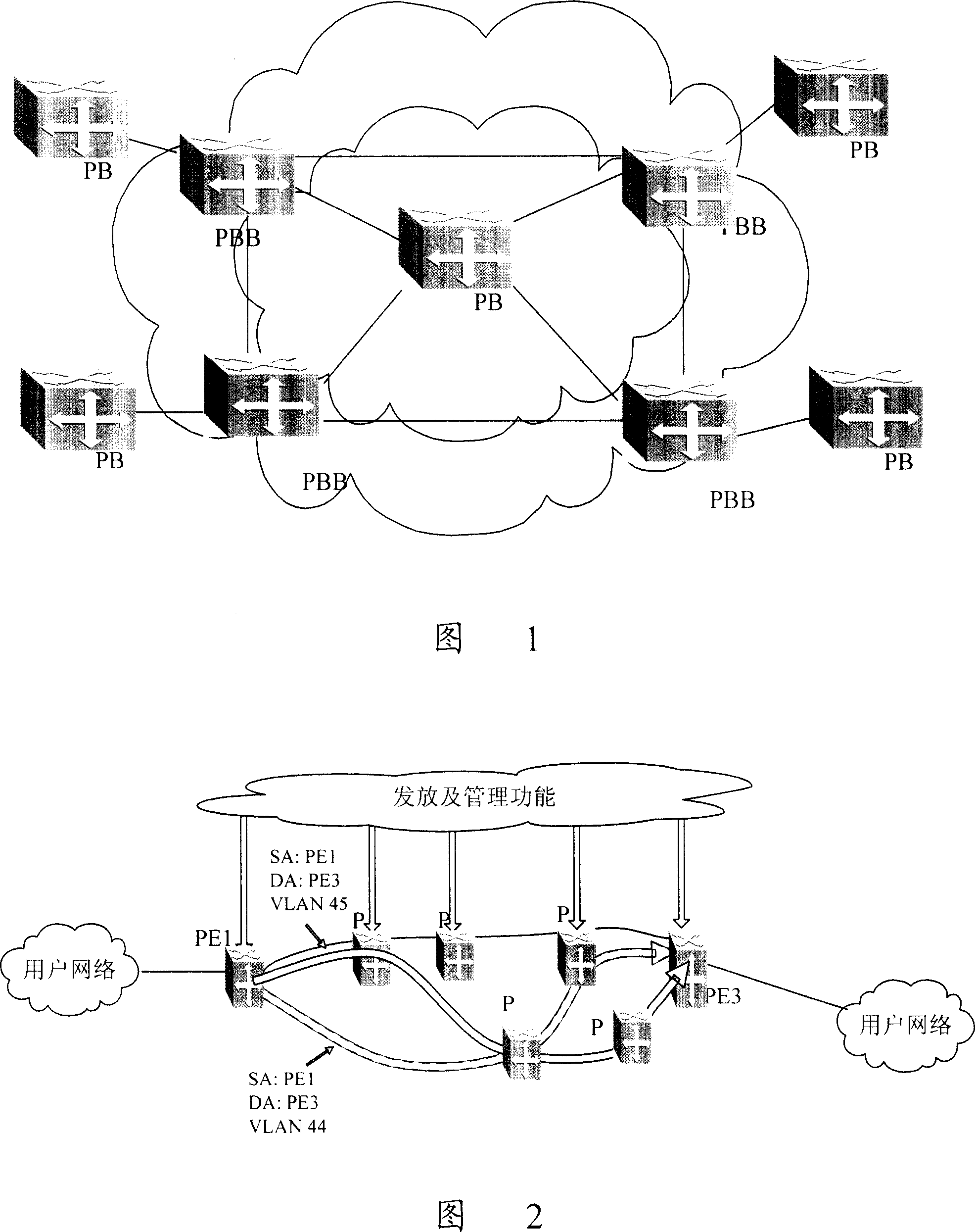
technical field [0001] The invention relates to the data transmission technology of the two-layer network, especially the data forwarding method and network and node equipment in the two-layer network. Background technique [0002] At present, many technologies are implemented in networks using Ethernet technology, such as: Provider Backbone Transport (PBT), which is a provider backbone bridge network (Provider Backbone Transport, PBT) defined in IEEE 802.1ah (also known as MACinMAC). Emerged on the basis of Backbone BridgesNetwork). [0003] The purpose of IEEE 802.1ah is to define a new architecture and bridge protocol compatible with and interoperable with 802.1ad provider bridge (ProviderBridge, PB), so that multiple PB networks can be connected together to achieve at least 2 24 A business virtual local area network (Virtual LAN, VLAN). [0004] The structure of the carrier's backbone bridge network defined by 802.1ah is shown in Figure 1. This network is based on 802....

Claims


Application Information

Patent Timeline
IPC IPC(8): H04L12/56H04L29/06H04L12/24H04L12/28H04L45/74
CPCH04L29/12839H04L12/4633H04L61/6022H04L12/4641H04L2101/622H04L45/74
Inventor 郑若滨李宏宇
Owner HUAWEI TECH CO LTD
Learn More