
Wafer transfer method and grinding device

A wafer and grinding technology, applied in transportation and packaging, grinding/polishing equipment, and machine tools suitable for grinding workpiece planes, etc., can solve problems such as uneconomical consumption, water waste, and difficulty in wafer peeling, and reduce water supply volume effect

Active Publication Date: 2008-02-20
DISCO CORP
View PDF2 Cites 14 Cited by
  • Summary
  • Abstract
  • Description
  • Claims
  • Application Information

AI Technical Summary

Problems solved by technology

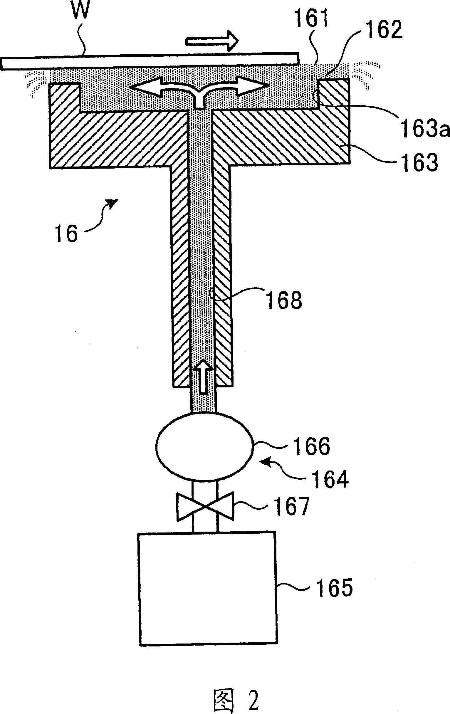
[0006] However, although the flow rate of water supplied to the upper surface of the holding table can be small in order to form a water layer for centering of the wafer, when the flow rate of water supplied is small, the surface tension on the wafer is strengthened, even if it is adsorbed by the transfer arm. The suction cup of the wafer rises, and the peeling of the wafer becomes difficult
Therefore, in reality, in order to overcome the surface tension of the water layer and facilitate the adsorption and detachment of the wafer by the suction cup, supplying unnecessary flow rate (for example, 2 liters / minute) of water for centering weakens the Centering under the state of surface tension, resulting in waste of water
Especially in the grinding equipment, since the part of the holding table for positioning is not directly involved in the wafer processing, the consumption of excess water in this part is very uneconomical.

Method used


Image

  • Wafer transfer method and grinding device
  • Wafer transfer method and grinding device
  • Wafer transfer method and grinding device

Examples


Embodiment Construction

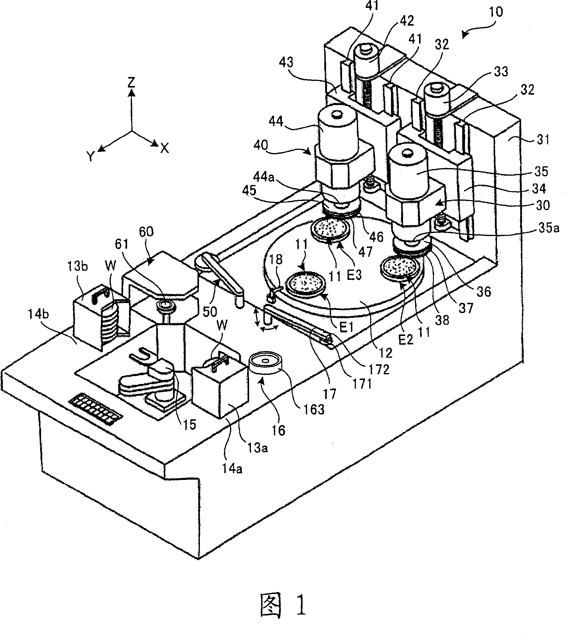
[0018] Hereinafter, a wafer transfer method which is the best mode for carrying out the present invention and a grinding device for carrying out the wafer transfer method will be described with reference to the drawings.

[0019] FIG. 1 is a perspective view showing the appearance of a grinding device that implements the wafer transfer method of the present embodiment. The grinding device 10 has: three chuck tables 11, which suck and hold the wafer W; a rotating rotating table 12, which supports the chuck tables 11 so as to be freely rotatable, respectively; and wafer cassette mounting portions 14a, 14b, which Wafer cassettes 13a and 13b containing wafers W are placed; a carry-in and unload unit 15 that unloads wafers W from wafer cassette 13a placed on the wafer cassette mounting portion 14a, and stores the ground wafer W into Placed in the wafer cassette 13b on the cassette placement portion 14b; positioning unit 16, which centrally positions the wafer W carried out by the carry...


PUM


Abstract

The invention provides a wafer transfer method and a grinding device. Even in a state where the surface tension is strong and the amount of water supplied to hold the wafer on the holding table via the water layer is reduced, the wafer can be peeled from the water layer to be transported. The sucker (171) of the transfer unit (17) is held on the suction position of the wafer (W) on the holding table (163) through the water layer (162), and is set as the sucker center (φ2) so as to be aligned with the wafer (W). ) of the center (φ1) of the wafer does not coincide with the state of being sucked by the chuck (171), and the transfer arm (172) is raised in the vertical direction to transfer, thereby, it is different from the position sucked at the center of the wafer. Compared with the situation, the adsorption and detachment of the wafer (W) from the water layer (162) becomes extremely easy.

Description

Technical field [0001] The present invention relates to a wafer transport method and a grinding device. Background technique [0002] In order to form a semiconductor on the surface, a grinding device is used to grind the surface of a silicon wafer in advance, or a plurality of ICs (Integrated Circuits) and LSIs (Large Scale Integrations) are formed on the surface. The back surface of the semiconductor wafer of the semiconductor chip such as) is ground to form the silicon wafer or the semiconductor wafer to a predetermined thickness. In the grinding device, when the wafer is automatically transferred from the wafer cassette to the chuck table, the positioning of the wafer is necessary, and the technology of positioning the wafer at a predetermined position using the surface tension of water is known (for example, refer to the patent Literature 1, 2). That is, the upper surface of the holding table for positioning is continuously supplied little by little to form a water layer on ...

Claims


Application Information

Patent Timeline
IPC IPC(8): H01L21/677B24B7/22
Inventor 小泽宽修
Owner DISCO CORP
Learn More