Automobile electrical signal test method and device
A test device and electrical signal technology, applied in the field of electrical signal measurement of automotive electronic control system sensors, actuators and ECUs, can solve problems such as damage to connectors or wiring harnesses, failure to pick up and measure electrical signals, damage to protection devices, etc.
- Summary
- Abstract
- Description
- Claims
- Application Information
AI Technical Summary
Problems solved by technology
Method used
Image
Examples
Embodiment Construction
[0012] specific implementation plan
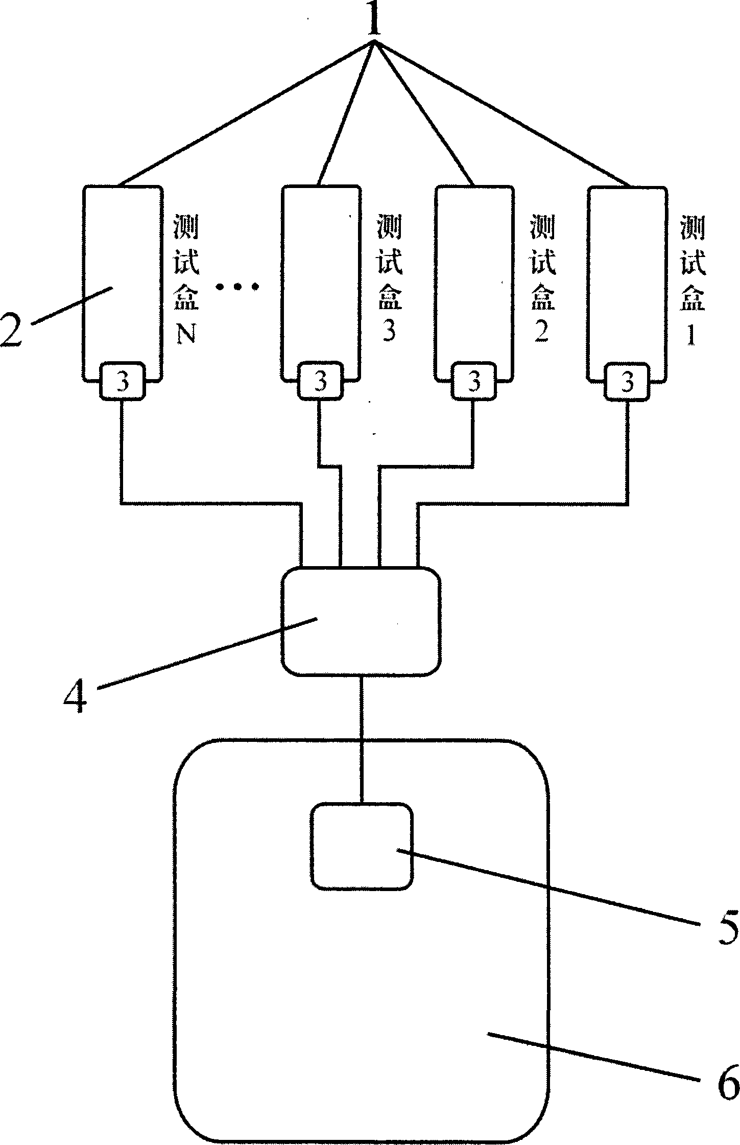
[0013] As shown in the figure, the electric signal test part includes a test box (1) and a test panel (2). The circuit diagram of this type of automotive electronic control system is drawn on the test panel (2), and standard general-purpose test terminals are embedded on the circuit diagram. The test terminal The connection line is connected to the internal interface (3) through the connector, and the external interface (4) is connected to the electronic control unit (5) of the automobile or the automobile test bench (6), and then it can be installed on the test box (1) The test panel (2) directly uses multimeters and oscilloscopes to measure various electrical signals, including the resistance, voltage, frequency, pulse width, duty cycle, oscilloscope and signal lines of various sensors, actuators and ECUs in automotive electronic systems conductivity etc.
[0014] The external interface (4) not only plays the role of wiring harness tran...
PUM
 Abstract
Description
Claims
Application Information
 - R&D
- Intellectual Property
- Life Sciences
- Materials
- Tech Scout
- Unparalleled Data Quality
- Higher Quality Content
- 60% Fewer Hallucinations
Browse by: Latest US Patents, China's latest patents, Technical Efficacy Thesaurus, Application Domain, Technology Topic, Popular Technical Reports.
© 2025 PatSnap. All rights reserved.Legal|Privacy policy|Modern Slavery Act Transparency Statement|Sitemap|About US| Contact US: help@patsnap.com

