
Pressing ball forming method and device

A molding device and molding method technology, applied in the direction of mold extrusion granulation, etc., can solve the problems of difficult demoulding, low work efficiency, and high processing costs, and achieve the effects of stable and reliable molding process, improved product quality, and reduced processing costs

Inactive Publication Date: 2008-02-20
房建春
View PDF0 Cites 14 Cited by
  • Summary
  • Abstract
  • Description
  • Claims
  • Application Information

AI Technical Summary

Problems solved by technology

The disadvantage of this structure is that because the forming parts of the upper and lower mold cores are hemispherical, the air inside the powder is difficult to discharge during the rapid compression process, which will easily cause interlayers and cracks in the pressed sphere, which will affect the intrinsic nature of sphere forming. quality
At the same time, this pressing method, because the sphere is easy to adhere to the upper mold core or the lower mold core, causes difficulty in demoulding, low work efficiency, and the external quality of the formed sphere is not high.
Although there are some improvement methods, such as changing the shape of the pressed ball to a cylindrical or elliptical shape to improve the demoulding problem, the grade and quality of the non-spherical products are obviously not up to standard; in addition, a large tonnage of dry powder is required during the pressing process Material pressing machine processing, the processing cost is also higher
[0003] Therefore, the existing powder pressing ball forming technology has the problems of low qualified rate of pressed products, low work efficiency, and high processing cost.

Method used


Image

  • Pressing ball forming method and device
  • Pressing ball forming method and device

Examples


Embodiment Construction

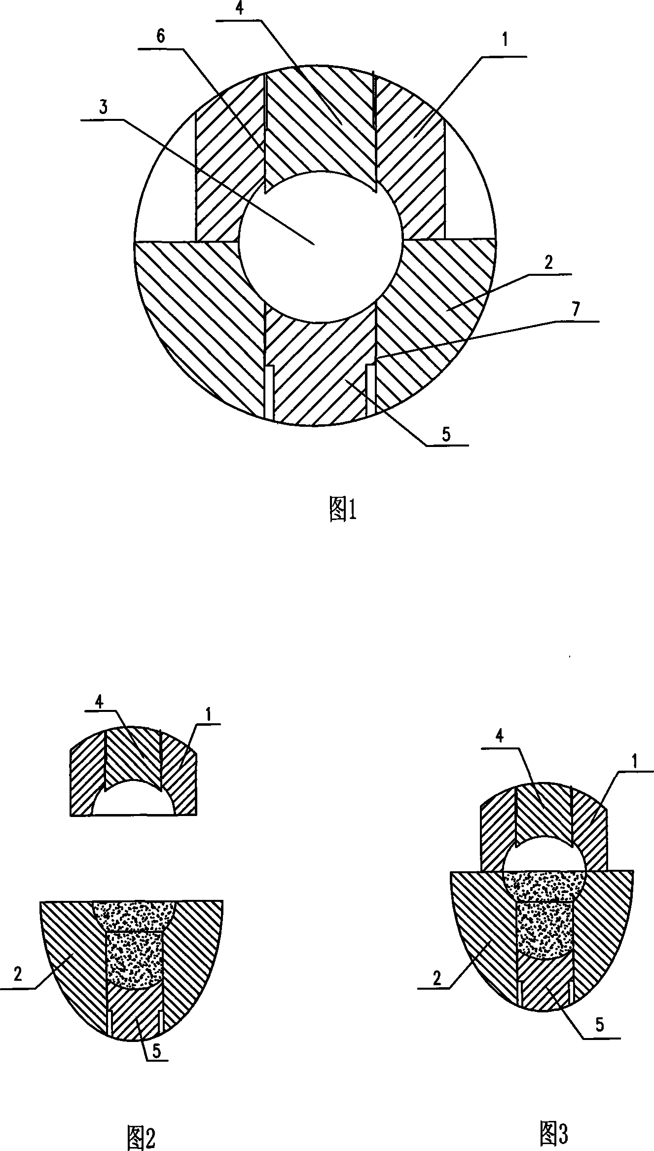
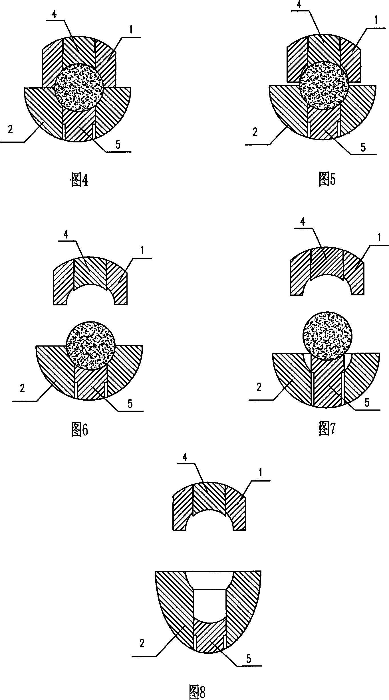
[0033] As shown in Figures 2 to 8, a pressing ball molding method of the present invention is to add upper and lower mold cores respectively in the upper and lower mold frames of the existing pressing ball molding device, and through the upper and lower mold frames The mold core moves longitudinally, and the powder fed into the mold frame is pressed into a spherical body and the demoulding process is completed.

[0034] Described pressing ball molding method, it comprises following production steps:

[0035] a. The lower mold frame moves upward relative to the lower mold core, so that the upper part is a hemisphere, and the lower part is a cylinder;

[0036] b. Loading, sending the powder required for pressing the entire sphere into the material-holding cavity formed through the process of (a);

[0037] c. The upper die is connected downward to the lower die frame;

[0038] d. For ball forming, the upper mold continues to move downward, and drives the lower mold frame to mov...


PUM


Abstract

The present invention discloses a pressing ball molding method and device, comprising an upper die grid, a lower die grid, a global die cavity arranged between the upper die grid and the lower die grid, the characteristic technic proposal is that die cores are respectively arranged in the upper die grid and the lower die grid, the die core is movable arranged in the die grid, the global die cavity mainly consists of the upper die grid, the lower die grid and the die cores arranged in the die grids which are encircled, the connecting positions of the die cores and the die grid are provided with air-escape passages, compressing the powders which are sent into the die grid, by the vertical movement of the die grid corresponding to the die core, eliminating the air in the powders step by step, and pressing into a sphericity. The present invention has the advantages of high work efficiency, good presentation quality and low processing cost, has good value of market popularization.

Description

technical field [0001] The invention relates to the field of ball forming processing, and more specifically relates to a pressed ball forming method and device. Background technique [0002] At present, the powder pressing ball molding structure that appears on the market is mainly composed of upper and lower mold cores and a mold frame. The molding parts of the upper and lower mold cores are all set in a hemispherical shape. The core is inserted into the mold frame and combined with the lower mold core to form a spherical cavity. During the manufacturing process, the powder is filled into the mold cavity of the lower mold core, and then the upper mold core enters the mold cavity to close the mold. The powder in the mold cavity is compressed and combined into a sphere, and finally the sphere is taken out of the mold cavity. The disadvantage of this structure is that because the forming parts of the upper and lower mold cores are both hemispherical, the air inside the powder...

Claims


Application Information

Patent Timeline
IPC IPC(8): B01J2/22
Inventor 房建春
Owner 房建春
Learn More