Punch

A punching machine and hole-containing technology, which is applied in the field of punching machines, can solve the problems of cumbersome production of integral components and limited labor-saving effect, and achieve the effect of simple structure and fast punching action

Inactive Publication Date: 2008-02-13
JIANMING OFFICE APPLIANCE SHANGHAI
View PDF0 Cites 7 Cited by
  • Summary
  • Abstract
  • Description
  • Claims
  • Application Information

AI Technical Summary

Problems solved by technology

[0005] This kind of punching machine structure mainly uses the upper cover pressing part to pivot with the second pivot as the fulcrum, and then links the lower arm with the upper arm of the moment arm assembly, so that the lower arm also uses the second The pivot is used as the fulcrum to pivot downward, and then the punch that is linked with the pivot of the lower arm produces a displacement punching action; however, the upper arm of the moment arm assembly is pivoted with the upper cover, and the upper cover acts When pivoting, the power is only transmitted to the lower arm through the upper arm, and then the lower arm is linked with the punch to punch holes. This actuation technical means does not see a significant change in the torque, so its The labor-saving effect of the action is limited, and the overall components are cumbersome to make

Method used


Image

  • Punch
  • Punch
  • Punch

Examples


Embodiment Construction

[0017] Below in conjunction with accompanying drawing and specific embodiment the present invention is described in further detail:

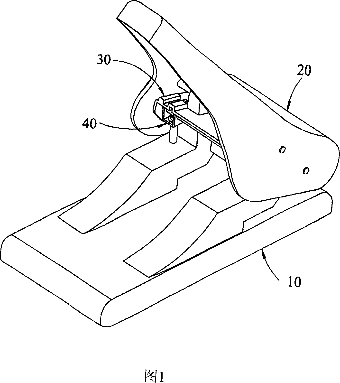
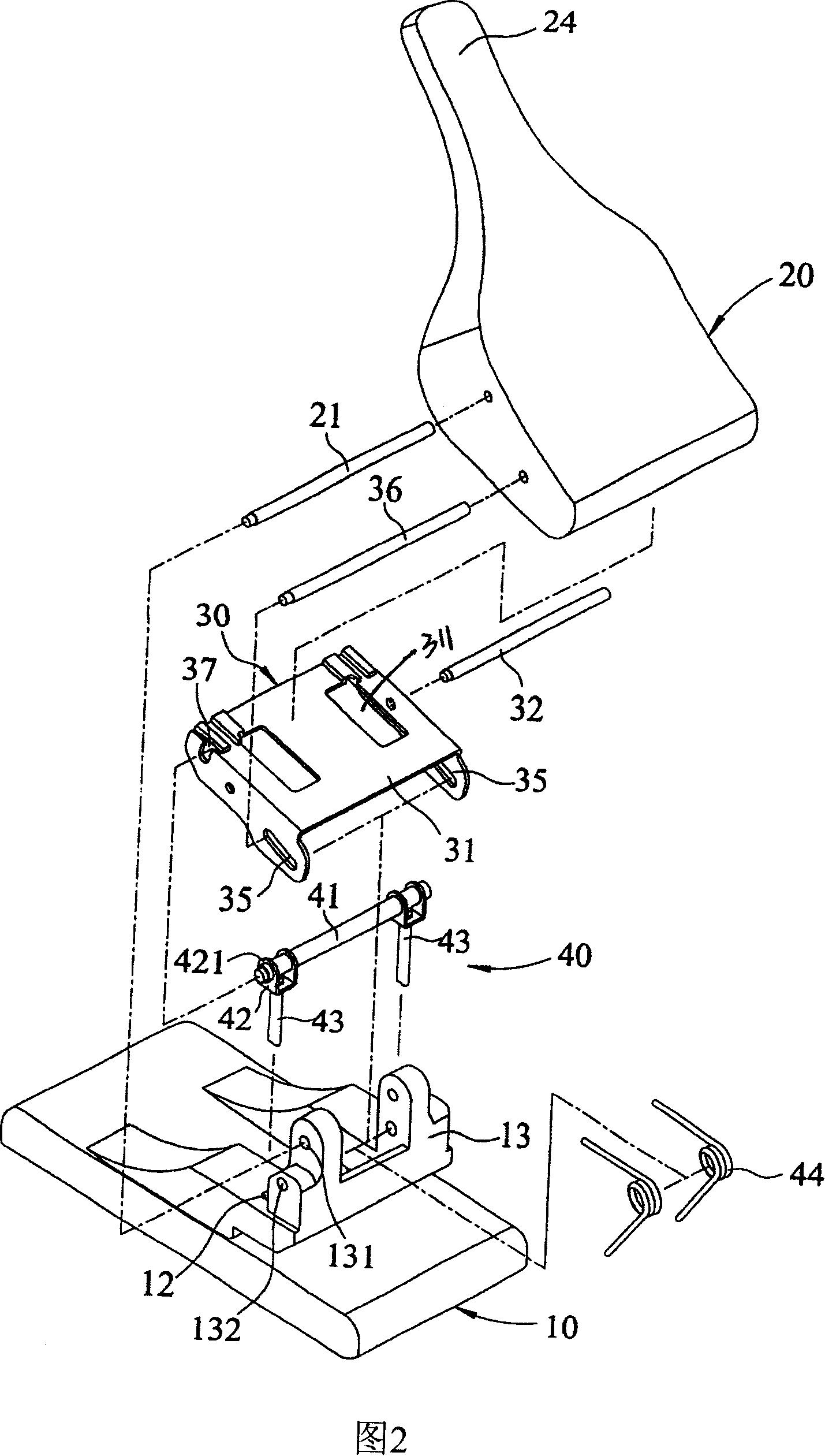
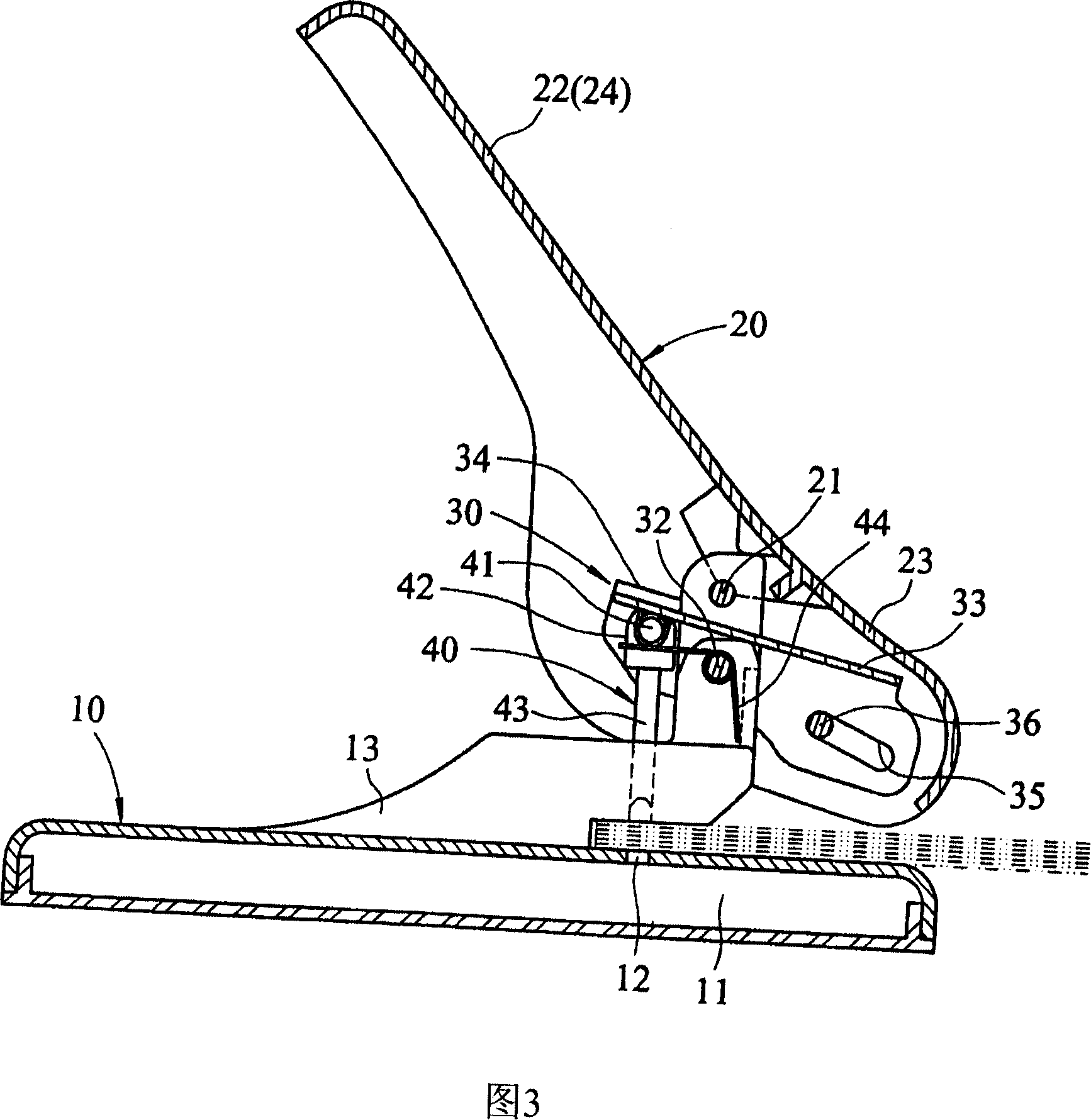
[0018] It can be seen from Fig. 1, Fig. 2 and Fig. 3 that the present invention includes: a base 10, an upper cover 20, a linkage group 30 and a punching part 40, wherein;

[0019] The base 10 is a pedestal body with a chamber 11 below, and two holes 12 are arranged above it, and two fixing seats 13 which are aligned side by side with each of the holes 12 are fixed on its top surface, the fixing seats 13 There are upper and lower pivot holes 131, 132 for pivot connection;

[0020] The upper cover 20 is pivoted through the pivot hole 131 on each of the fixing bases 13 with a first pivot rod 21, which can be rotated at a preset angle, and a first pivot is formed at both ends of the pivot point. The force application arm 22 and a first force resistance arm 23 which is linked, and the first force application arm 22 is set as a pressing part 24;

...


PUM


Abstract

The present invention relates to a punch comprising a base; at least two holes are equipped above the base and at least two fixing bases are fixed on the top of the base and aligned to the holes; an upper cover which is equipped on every fixing base by a pivot; a first force application arm of pressing part and a linked first force resistant arm are formed at both ends of the pivot connection points; a linked group which is equipped on every fixing base by linked base between the upper cover and the base; a secondary force application arm with a corresponding guided groove and a secondary force resistant arm with a slot are formed at both ends of the pivot connection points; the guided groove and the first force resistant arm are equipped by pivot; a punching piece which is equipped with a knife; the knife is extended to every fixing base and the base hole for displacement and connected with the secondary force resistant arm by pivot by a link lever; the first force application arm equipped on the upper cover is longer than the first force resistant arm and the secondary force application arm equipped on the linked base is longer than the secondary force application arm; in this way, the punching piece can punch faster and neatly; the pressing can save labor and the structure is simple.

Description

technical field [0001] The invention relates to a punching machine, in particular to a pressing structure of the punching machine. Background technique [0002] The hole punching machine is a cutting stationery. It uses its punch to punch holes and cut the paper below, so that the whole stack of paper forms neat and aligned holes, which is convenient for threading binders or ropes. Binding, to avoid fragmented documents that cannot be archived. [0003] Since the punching machine uses a pressing method to make a punch with a blade to punch holes in the paper, the industry's structural design of the punching machine focuses on how to save labor and cut quickly, so as to improve the punching of the paper. The speed and quality of the hole can play the maximum function of "doing more with less". [0004] It can be seen from Fig. 6 and Fig. 7 that the punching machine 50 includes: a hollow base 51 on which two perforations 52 are formed, and two fixing frames 53 respectively a...

Claims


Application Information

Patent Timeline
Patent Type & Authority Applications(China)
IPC IPC(8): B26F1/02B26D5/10B26D5/18
Inventor 黃建凯
Owner JIANMING OFFICE APPLIANCE SHANGHAI
Why Eureka
Try Eureka