


Quick Research
Generate reliable direction feasibility study reports for your R&D in just a few steps.

Technical Q&A
Discover and master advanced knowledge NOW. Basics, ideas, possibilities, all at once.

Find Solutions
As an expert in R&D theories, this can generate solutions to your technical problems instantly.

Evaluate Feasibility
Analyze your overall solution with one click, know your potential R&D risks in advance.

Monitor Landscape
Get weekly tech updates, stay abreast of the latest tech innovations and key insights.
Joint moment sensor providing torque and bending moment overload protection
A technology of overload protection and joint torque, applied in torque measurement, instrument, power measurement and other directions, can solve problems such as overload protection, and achieve the effect of safe and reliable system operation
- Summary
- Abstract
- Description
- Claims
- Application Information
AI Technical Summary
Problems solved by technology
Method used
Image


Examples
specific Embodiment approach 1
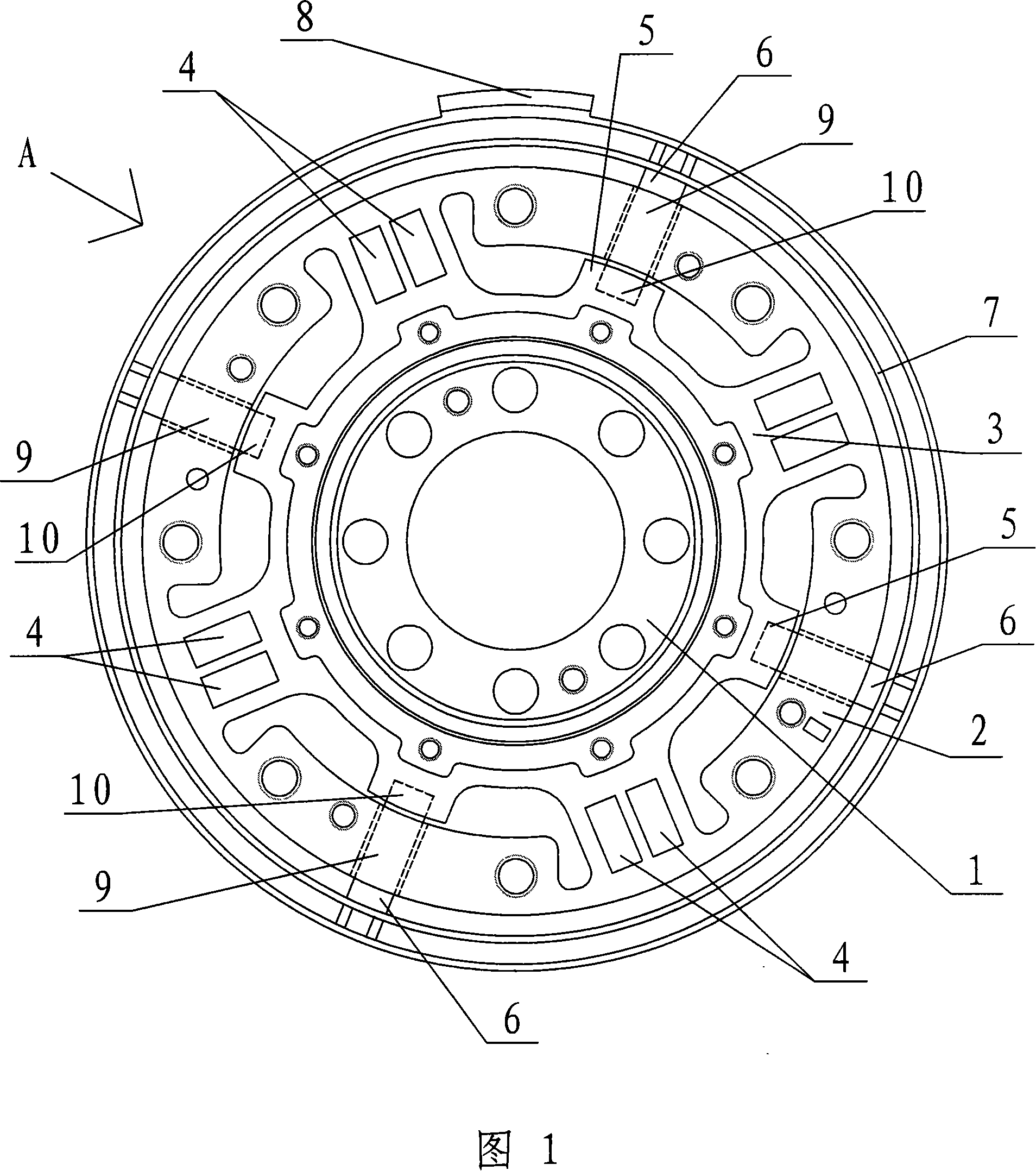
[0006] Specific implementation mode 1: Referring to Figures 1 to 3, this embodiment consists of an input connection flange 1, an output connection flange 2, four sensor strain beams 3, eight strain gauges 4, four overload protection beams 5 and Composed of four protective pins 6, the two ends of the four sensor strain beams 3 are respectively fixedly connected with the outer edge of the input connection flange 1 and the inner edge of the output connection flange 2, and are evenly distributed along the circumference of the input connection flange 1. distribution, each sensor strain beam 3 is provided with two strain gauges 4, the four strain gauges 4 on the two sensor strain beams 3 in the same diameter direction form a full bridge, and the four overload protection beams 5 are respectively arranged on Two adjacent sensor strain beams 3 are fixedly connected to the outer edge of the input connection flange 1, blind holes 10 are respectively opened on each overload protection beam...
specific Embodiment approach 2
[0007] Embodiment 2: Referring to FIG. 1 and FIG. 2 , the difference between this embodiment and Embodiment 1 is that the eight strain gauges 4 arranged on the four sensor strain beams 3 are located on the same plane. Other compositions and connections are the same as in the first embodiment. The eight strain gauges 4 are pasted on the whole plane, which can make the position of the strain gauges 4 more accurate.
specific Embodiment approach 3
[0008] Specific embodiment 3: Referring to FIG. 1 and FIG. 2 , this embodiment adds a sealing ring 7 on the basis of specific embodiment 1, and the sealing ring 7 is arranged on the output connecting flange 2 . Other compositions and connections are the same as in the first embodiment. The torque sensor is used on the output side of the joint to transmit torque to the next joint. The sealing ring 7 on the torque sensor can cooperate with other parts of the joint (such as the joint shell) to form a contact seal (such as a felt seal) or a non-contact seal (such as labyrinth seal) to protect the inside of the joint.
PUM
 Abstract
Description
Claims
Application Information
 - R&D Engineer
- R&D Manager
- IP Professional
- Industry Leading Data Capabilities
- Powerful AI technology
- Patent DNA Extraction
Browse by: Latest US Patents, China's latest patents, Technical Efficacy Thesaurus, Application Domain, Technology Topic, Popular Technical Reports.
© 2024 PatSnap. All rights reserved.Legal|Privacy policy|Modern Slavery Act Transparency Statement|Sitemap|About US| Contact US: help@patsnap.com