
Hand-operated electrical machine tool and coupler for a hand-operated electrical machine tool

A hand-operated, power tool technology, used in hand-held lawn trimmers, cutting tools, gardening tools/equipment, etc., can solve problems such as cumbersome operation

Inactive Publication Date: 2008-02-06
ROBERT BOSCH GMBH
View PDF0 Cites 1 Cited by
  • Summary
  • Abstract
  • Description
  • Claims
  • Application Information

AI Technical Summary

Problems solved by technology

The operation of this sliding part is relatively cumbersome

Method used


Image

  • Hand-operated electrical machine tool and coupler for a hand-operated electrical machine tool
  • Hand-operated electrical machine tool and coupler for a hand-operated electrical machine tool
  • Hand-operated electrical machine tool and coupler for a hand-operated electrical machine tool

Examples


Embodiment Construction

[0021] Identical elements are identified identically in the various figures.

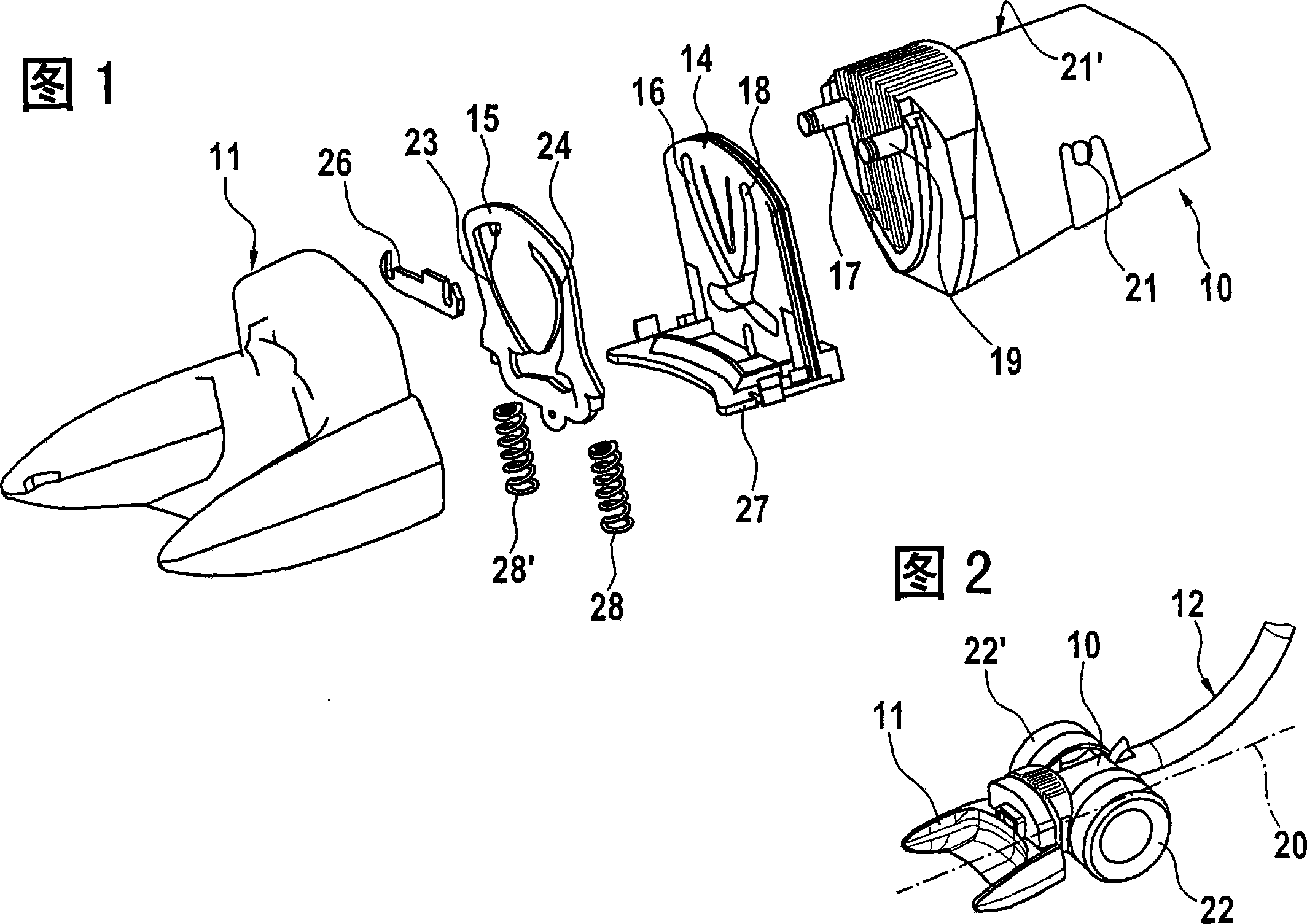
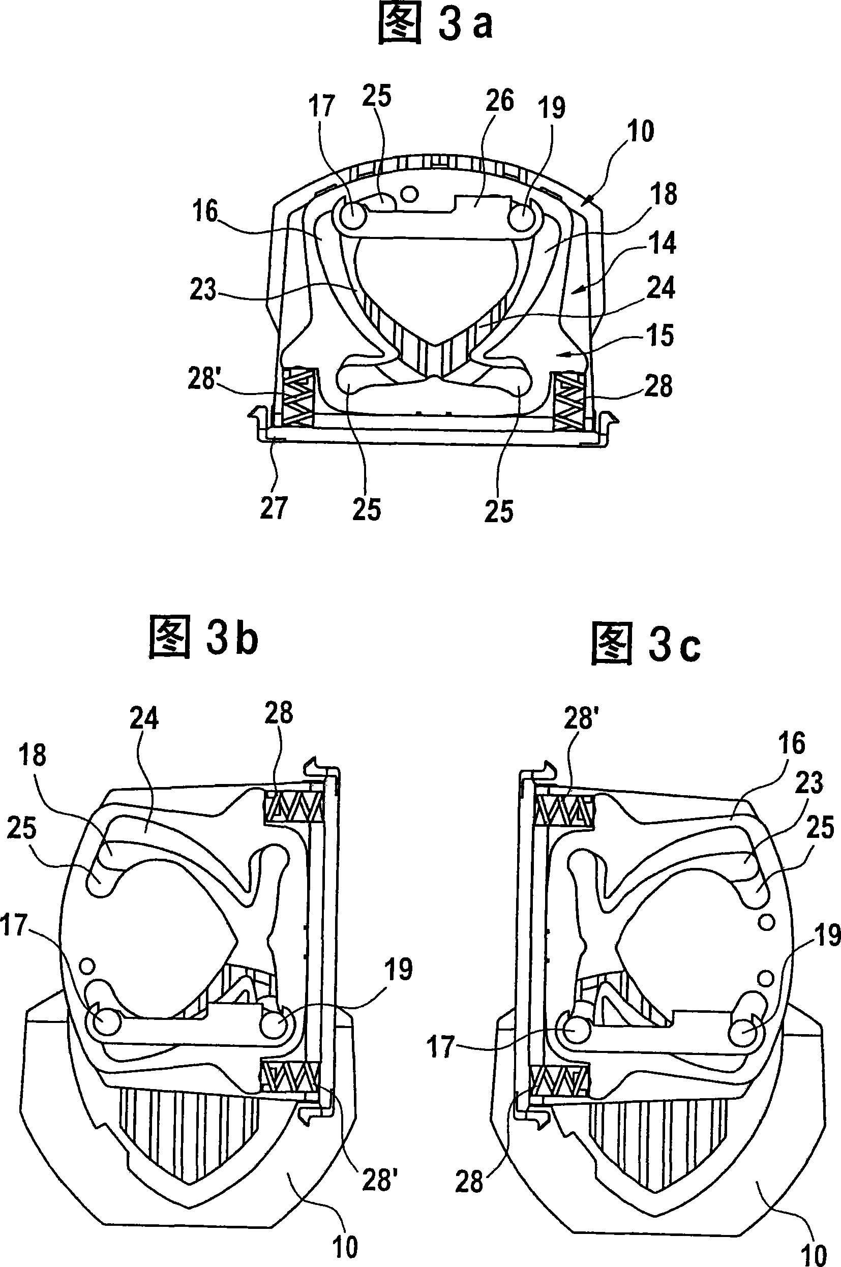
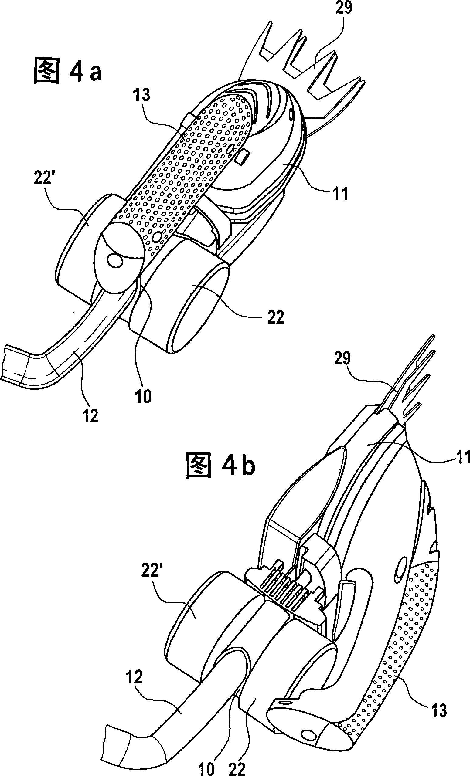
[0022] FIG. 1 shows an exploded view of an embodiment of a hand-held electric power tool according to the invention, designed as a lawnmower, with a rod holder 10 and a fork-shaped tool holder 11 . A travel rod 12 not shown in FIG. 1 can be connected to the rod clamp 10 . A tool (not shown), for example a cutting tool, can be clamped or locked in the tool holder 11 .

[0023] A coupling is provided between the tool holder 11 and the rod holder 10 . According to the invention, the coupling has a pivot guide which enables a relative rotation between the tool holder 11 and the rod holder 10 . The coupling is connected to the tool holder 11 by means of a fastening element 26 in such a way that a unit pivotable relative to the bar holder 10 is formed.

[0024] The coupling comprises a substantially plate-shaped base element 14 and a locking element 15 . Both elements 14, 15 each have a pivot guide. ...


PUM


Abstract

The invention relates to a hand-operated electric power tool, in particular a lawnmower, comprising at least one rod holder (10) and a tool holder (11), wherein a moving rod (12) can be connected to the rod holder (10). The invention proposes to provide a coupling between the tool clamp (11) and the rod clamp (10), wherein the coupler has a swing guide device, which makes the connection between the tool clamp (11) and the rod clamp (10) Relative rotation between them is possible. In addition, the invention also relates to a coupling for a hand-operated electric power tool.

Description

technical field [0001] The invention relates to a hand-operated electric power tool, in particular a lawnmower, comprising at least one pole clamp and a tool clamp, wherein a moving rod can be connected to the pole clamp; the invention also relates to a hand-operated power tool machine connector. Background technique [0002] The work of the hand-operated electric power tool can be facilitated in part by the fact that the tool holder is designed to be pivotable. The deflection of the tool has proven useful, for example, when cutting inaccessible branches or trimming hedges. When mowing grass, a cutting head that can be swiveled about the central axis of the power tool is advantageous for cutting the edge of the grass. [0003] It is known in the prior art to lock the manual rotation mechanism required for the pivoting movement by means of a crown hinge which can be arranged at the free end of a travel lever which can be connected to a power tool. In principle, a travel le...

Claims


Application Information

Patent Timeline
Patent Type & Authority Applications(China)
IPC IPC(8): A01D34/90A01D34/84A01G3/06A01G3/037A01G3/047
CPCA01G3/067
Inventor U·M-博伊森F·班特尔
Owner ROBERT BOSCH GMBH
Learn More