
Vehicle and control method of vehicle

A vehicle and control component technology, applied in the field of vehicle and vehicle control, can solve problems such as time required

Inactive Publication Date: 2008-01-30
TOYOTA JIDOSHA KK
View PDF1 Cites 25 Cited by
  • Summary
  • Abstract
  • Description
  • Claims
  • Application Information

AI Technical Summary

Problems solved by technology

That is to say, it takes time to set the target speed.

Method used


Image

  • Vehicle and control method of vehicle
  • Vehicle and control method of vehicle
  • Vehicle and control method of vehicle

Examples


Embodiment Construction

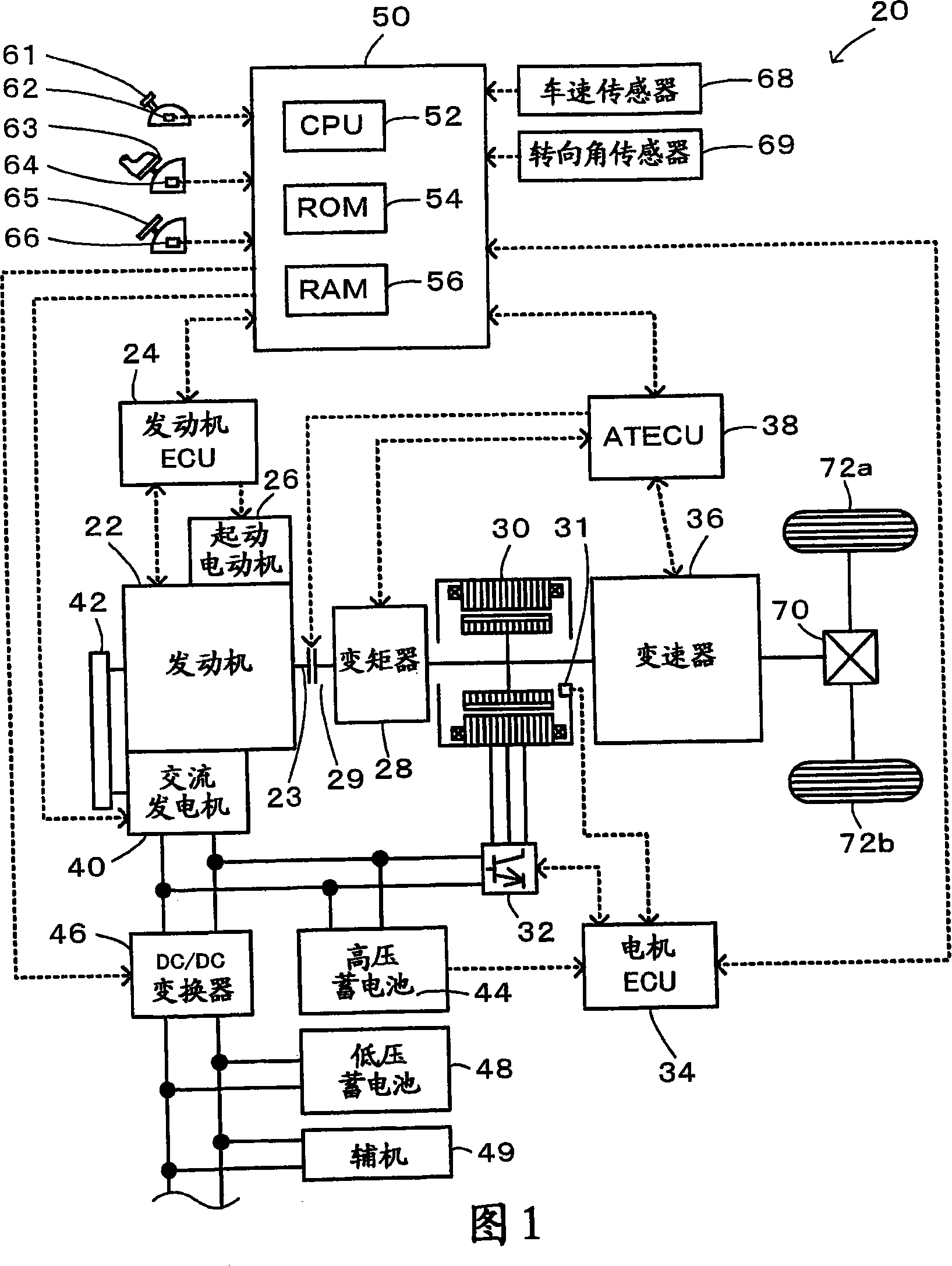
[0039] A mode for carrying out the present invention will be described below as a preferred embodiment with reference to the accompanying drawings. FIG. 1 schematically shows the structure of a hybrid vehicle 20 in one embodiment of the present invention. As shown in FIG. 1 , a hybrid vehicle 20 of the present embodiment includes an engine 22, a torque converter 28 connected to a crankshaft 23 or an output shaft of the engine 22 through a damper (not shown), and a torque converter 28 connected to the output shaft through a clutch 29. The torque converter 28 and the transmission 36 are connected to the drive wheels 72 a and 72 b through the differential 70 , and the electric motor 30 which outputs power from the transmission 36 and inputs power to the transmission 36 and has power generation capability. The hybrid vehicle 20 also includes an alternator 40 that is connected to the crankshaft 23 of the engine 22 through a belt 42 and generates electric power using the output powe...


PUM


Abstract

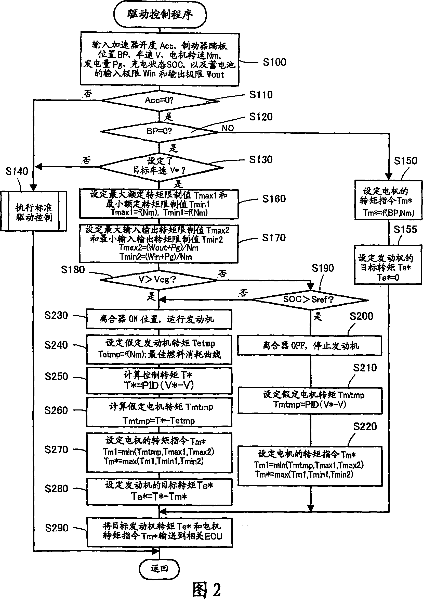
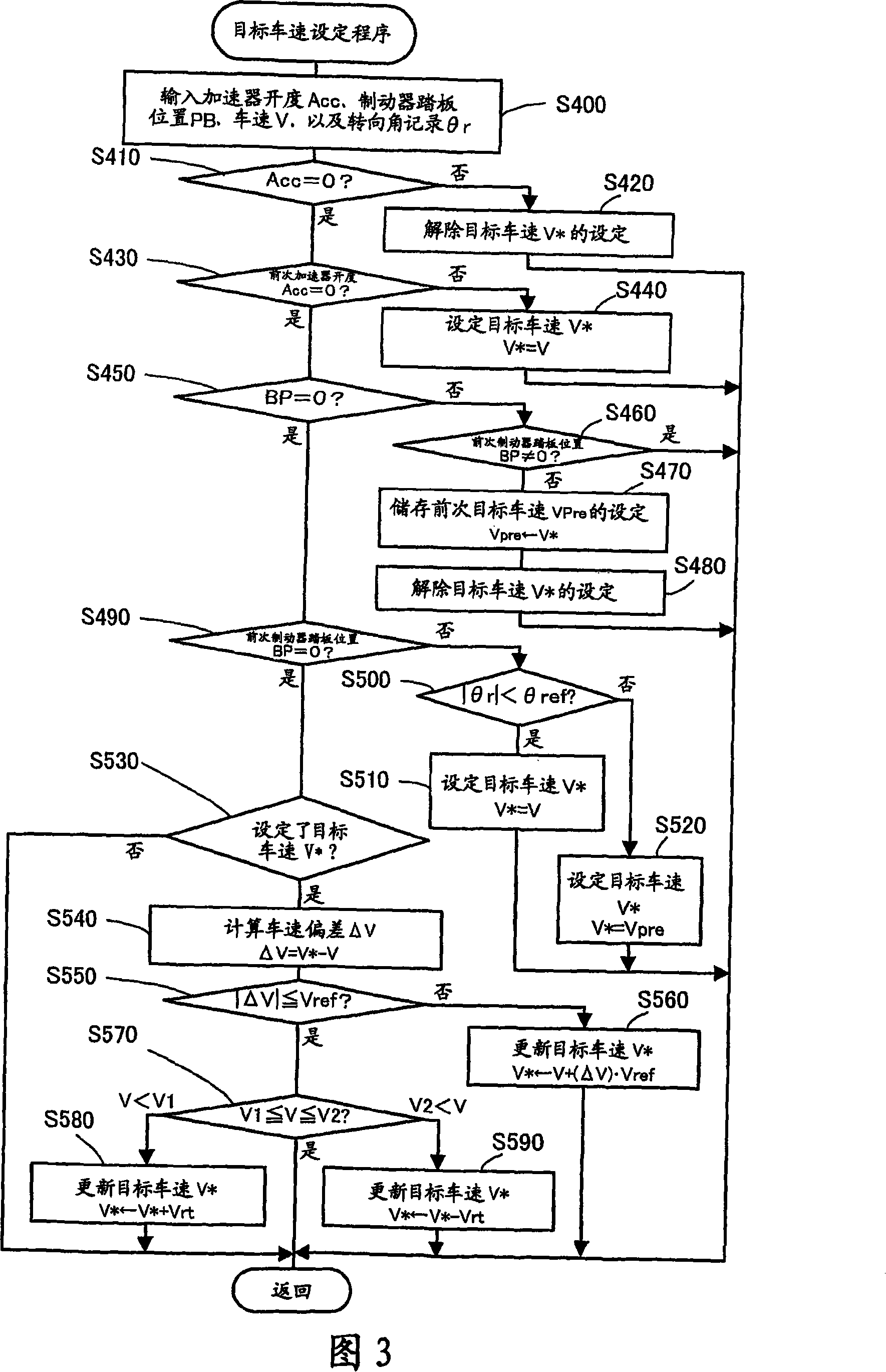
In the vehicle of the present invention, when the driver releases the depressed accelerator pedal, the drive control sets the vehicle speed V at that time as the target vehicle speed V* (step S440). The engine and the motor for outputting driving force are controlled to drive the vehicle at the target vehicle speed V*. When the driver steps on the relaxed brake pedal, the drive control stores the target vehicle speed V* set before the driver depresses the brake pedal as the previous target vehicle speed Vpre and cancels the setting of the target vehicle speed V* (steps S470 and S480 ). In response to the driver's subsequent release of the brake pedal, the drive control sets the vehicle speed V at this time as the target vehicle speed V* (step S510) and resumes constant speed (cruising) driving. When the driver turns the steering wheel to or beyond a predetermined degree for left or right turn, the driving control sets the previous target vehicle speed Vpre to the target vehicle speed V* (step S520) and restarts the constant speed driving. This arrangement ensures easy and quick start of constant speed (cruising) driving and enables constant speed (cruising) driving according to changes in the driving state.

Description

technical field [0001] The present invention relates to a vehicle and a control method for the vehicle. Background technique [0002] A proposed technique sets a target vehicle speed equal to a constant vehicle speed maintained for a predetermined period of time from a driver's ON operation of a main switch for constant-speed drive control, and The vehicle is driven at a constant speed at the target vehicle speed (for example, see Japanese Patent Laid-Open Publication No. 2006-6682). Such a proposed vehicle releases the constant speed drive in response to a driver's accelerator on operation or brake on (brake on) operation. Contents of the invention [0003] The prior art technology requires the driver to ON-operate the main switch for constant speed drive control to start the constant speed drive. The prior art technology can set the target vehicle speed for constant speed driving only after the vehicle remains at the constant speed for a predetermined period of time. ...

Claims


Application Information

Patent Timeline
Patent Type & Authority Applications(China)
IPC IPC(8): B60K31/04B60K6/44B60K6/448B60K6/52B60K6/54B60K31/00B60L50/16B60W10/02B60W10/06B60W10/26B60W20/00F02D29/00F02D29/02
CPCY02T10/6286B60W2540/10B60W2520/10B60W2540/12B60K1/02B60W10/06Y02T10/6234B60K6/48B60K6/442B60W20/00B60W10/08Y02T10/6221B60W2720/10B60L7/14B60L15/20B60L15/2027B60L15/2045B60L2220/14B60L2220/16B60L2240/12B60L2240/14B60L2240/421B60L2240/423B60L2240/441B60L2240/443B60L2240/486B60L2240/642B60L2250/28B60L2260/26B60L2260/28Y02T90/16Y02T10/70Y02T10/72B60L50/16B60L58/14B60L58/15Y02T10/62Y02T10/64Y02T10/7072B60W2540/18B60W30/143
Inventor 奥田弘一田畑满弘
Owner TOYOTA JIDOSHA KK
Learn More