IC card pop-out device
A card box and card part technology, which is applied to instruments, computer parts, transmission record carriers, etc., can solve the problems of inconvenience for users of cards, swallowing cards, and waiting for vehicles to be excluded, so as to achieve stable and reliable work, ensure normal operation, The effect of reducing operational failures
- Summary
- Abstract
- Description
- Claims
- Application Information
AI Technical Summary
Problems solved by technology
Method used
Image
Examples
Embodiment 1
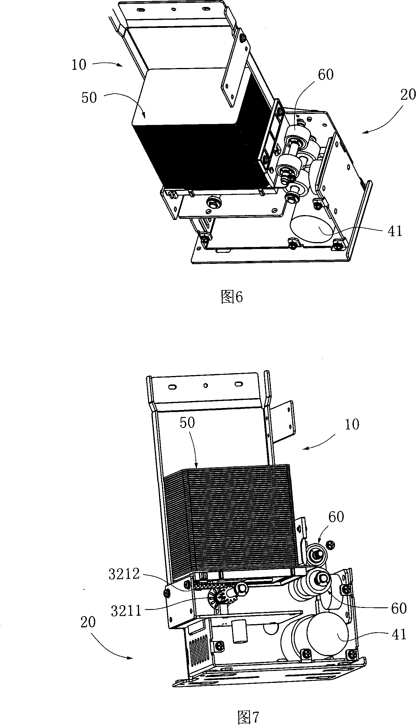
[0026] As shown in Figure 1, the IC card spit card device of the present invention comprises IC card case 10, the cabinet 20 that is located at the IC card case below, IC card operating mechanism 30 and driving mechanism 40. Described IC card box 10 comprises base plate 12, front side plate 13 and side plate 14, and the front portion of IC card box 10 is provided with IC card entrance and exit 11, and IC card entrance and exit 11 (seeing Fig. 2) places are provided with two can The forward and reverse card feeding wheel 60 is used for sending in or sending out the IC card 50 . The gist of the present invention is that the running mechanism 30 is a card pushing mechanism that reciprocates along the card in and out direction. As shown in Figure 2, this card pushing mechanism comprises push plate 31 and transmission mechanism 32, and push plate 31 is movably connected to the underside of the bottom plate 12 of IC card case, on push plate 31, be far away from one end end of IC car...
Embodiment 2
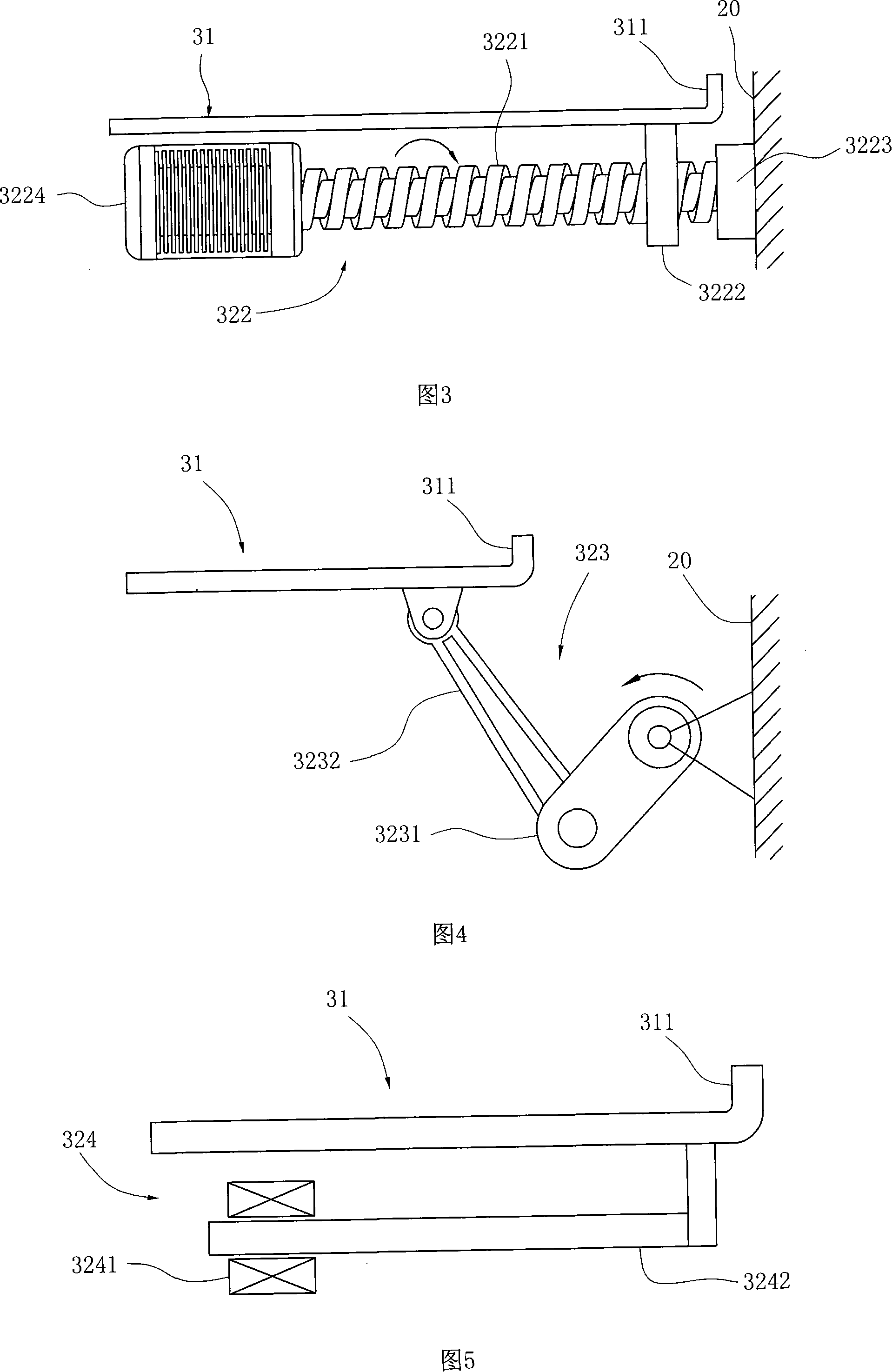
[0028] The basic structure is the same as that of Embodiment 1, the only difference being the transmission mechanism of the card pushing mechanism. In this example, the transmission mechanism 32 is a screw mechanism. As shown in FIG. 3 , the screw mechanism 322 is composed of a screw 3221, a nut 3222 and a bearing 3223, wherein the nut 3222 is fixedly connected to the bottom of the push plate 31 at an end away from the IC card inlet and outlet 11. , the axis of the screw hole is parallel to the push plate 31, the screw 3221 passes through the nut 3222 parallel to the push plate 31 and is threadedly connected with it, and its two ends are respectively connected with the motor 3224 and the bearing 3223, and the bearing 3223 is fixed on the side wall of the cabinet 20 . When the motor 3224 rotates forward or reversely, the push plate 31 is driven forward or backward by the thread transmission between the screw rod 3221 and the nut 3222 of the screw mechanism 322, and the IC card ...
Embodiment 3
[0030]The basic structure is the same as that of Embodiment 1, the only difference being the transmission mechanism of the card pushing mechanism. In this example, the transmission mechanism 32 is a connecting rod mechanism. As shown in FIG. 4, the connecting rod mechanism 323 is composed of a crank 3231 and a connecting rod 3232, wherein the two ends of the crank 3231 are respectively hinged to the side wall of the cabinet 20 and the connecting rod 3232. , the other end of the connecting rod 3232 is hinged to the end of the lower side of the push plate 31 close to the push card portion 311 . When the crank 3231 reciprocates around the hinge shaft, it drives the push plate 31 to move back and forth to complete the jamming action.
PUM
 Abstract
Description
Claims
Application Information
 - R&D
- Intellectual Property
- Life Sciences
- Materials
- Tech Scout
- Unparalleled Data Quality
- Higher Quality Content
- 60% Fewer Hallucinations
Browse by: Latest US Patents, China's latest patents, Technical Efficacy Thesaurus, Application Domain, Technology Topic, Popular Technical Reports.
© 2025 PatSnap. All rights reserved.Legal|Privacy policy|Modern Slavery Act Transparency Statement|Sitemap|About US| Contact US: help@patsnap.com


