
Method for optically transmitting polarisation multiplex signals

A technology for polarization multiplexing and wavelength division multiplexing signals, applied in polarization multiplexing systems, wavelength division multiplexing systems, etc., which can solve problems such as low power and achieve measurable improvements.

Inactive Publication Date: 2012-05-02
XIEON NETWORKS SARL
View PDF0 Cites 0 Cited by
  • Summary
  • Abstract
  • Description
  • Claims
  • Application Information

AI Technical Summary

Problems solved by technology

Another possibility for slightly reducing XpolM is to use a Raman amplifier, since the integrated power over the path is then relatively small

Method used


Image

  • Method for optically transmitting polarisation multiplex signals
  • Method for optically transmitting polarisation multiplex signals
  • Method for optically transmitting polarisation multiplex signals

Examples


Embodiment Construction

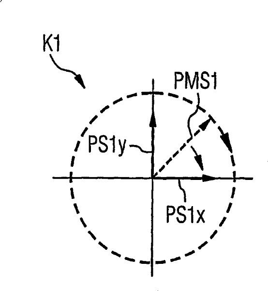
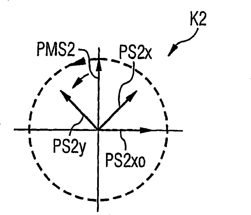
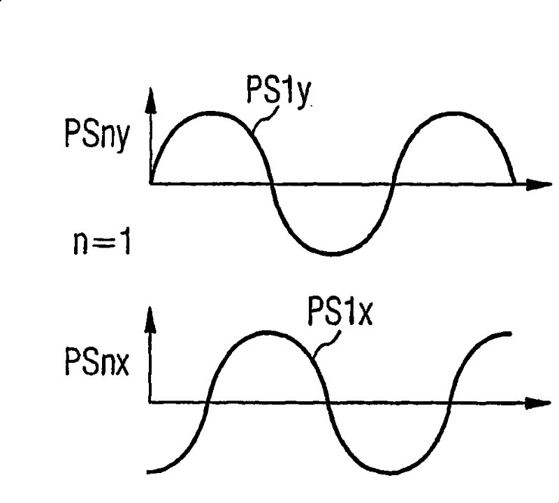
[0031]Figure 1 shows the polarization and phase angle values ​​of two POLMUX signals in adjacent POLMUX channels K1 and K2. The invention should be described with the aid of two adjacent channels, and applies correspondingly to the other channels. Two optical data signals PS1x and PS1y modulated with a logic 1 are transmitted in the first POLMUX channel K1. The amplitude of the E-field vector is shown as a transient diagram. The direction of propagation in the fiber is perpendicular to the drawing plane. The amplitude-modulated data signal PS1x is here horizontally polarized and the amplitude-modulated data signal PS1y is vertically polarized. Furthermore, the two signals have a mutual phase shift of +90° between their optical carrier signals (here PS1x eg -90°, FIG. 1b ), so that the resulting POLMUX signal PMS1 has a right circular polarization (shown in dotted line). The POLMUX signals in the other channels of the WDM system are likewise circularly polarized; however sin...


PUM


Abstract

For reducing the disturbance between the POLMUX signal (PMS1) and (PMS2), the POLMUX signal with inter-pushing carrier signal (TS1x, TS1y; TS2x, TS2y) are sent, so as to obtain the circular polarization of the separately generated POLMUX signal (PMS1, PMS2). Each of the second POLMUX signal (PMS2) herein can be transmitted opposite to the circular polarization. Therefore, for reducing the disturbance during the process of only transmitting one modulated data signal (PS1x) in POLMUX channel, each of the second POLMUX channel (K2) rotates 45 degrees from the polarization plane of the modulated data signals (PS2x, PS2y). The polarization multiplex signals (PMS1, PMS2, ?-) are generated in a modification and the polarizations generated by the polarization multiplex signals are mutual orthogonal in neighbouring channels.

Description

technical field [0001] The invention relates to a method for transmitting polarization multiplexed signals combined into wavelength division multiplexed signals. Background technique [0002] The transmission of data in a transmission system using multiplexing allows multiple users to use a transmission medium simultaneously, whereby the transmission capacity is significantly expanded. In the case of the optical wavelength division multiplexing method (English: "wavelength division multiplexing", abbreviated as WDM), the NRZ format has an intermediate wavelength (carrier wavelength) λ 1 ,...,λ N The N modulated optical signals (also referred to as data signals below) are combined into a broadband optical WDM signal through a wavelength division multiplexer, and transmitted in N channels. The WDM signal is thus a sum signal consisting of the data signals of N signals. The wavelength range or frequency range used for transmitting data signals is called a channel. [0003] ...

Claims


Application Information

Patent Timeline
Patent Type & Authority Patents(China)
IPC IPC(8): H04J14/06H04J14/02
CPCH04J14/06H04J14/02H04J14/0305
Inventor N·赫克W·帕特什D·泛登博恩
Owner XIEON NETWORKS SARL
Learn More