
Magnetron control method, magnetron service life judgment method, microwave generation device, magnetron service life judgment device, processing device, computer program, and storage medium

一种微波发生装置、控制方法的技术,应用在微波加热、电热装置、电/磁/电磁加热等方向,能够解决灯丝过加热、磁控管寿命缩短等问题,达到延长寿命的效果

Inactive Publication Date: 2008-01-16
TOKYO ELECTRON LTD
View PDF3 Cites 14 Cited by
  • Summary
  • Abstract
  • Description
  • Claims
  • Application Information

AI Technical Summary

Problems solved by technology

[0011]However, in the existing magnetron control method, in order to prevent overheating of the filament, the filament is increased or decreased in the opposite direction according to the increase or decrease of the output of the magnetron However, in reality, the temperature of the filament fluctuates greatly, and depending on the situation, the filament may be overheated, and the carbonized layer is excessively consumed, which greatly shortens the life of the magnetron.

Method used


Image

  • Magnetron control method, magnetron service life judgment method, microwave generation device, magnetron service life judgment device, processing device, computer program, and storage medium
  • Magnetron control method, magnetron service life judgment method, microwave generation device, magnetron service life judgment device, processing device, computer program, and storage medium
  • Magnetron control method, magnetron service life judgment method, microwave generation device, magnetron service life judgment device, processing device, computer program, and storage medium

Examples


Embodiment Construction

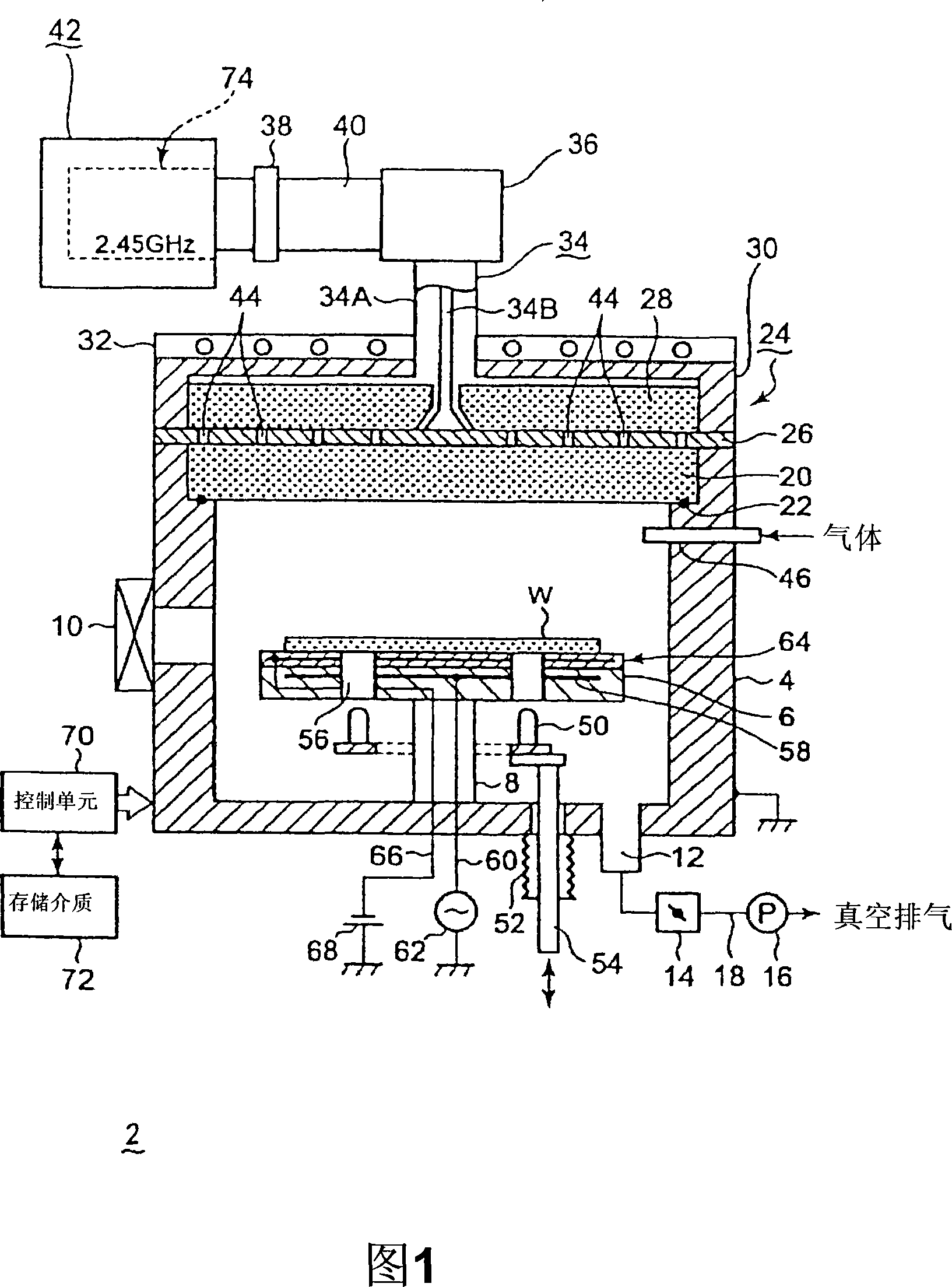
[0043] Hereinafter, an embodiment of a magnetron control method, a magnetron lifetime determination method, a microwave generator, a magnetron lifetime determination device, a processing device, and a storage medium of the present invention will be described with reference to the accompanying drawings.

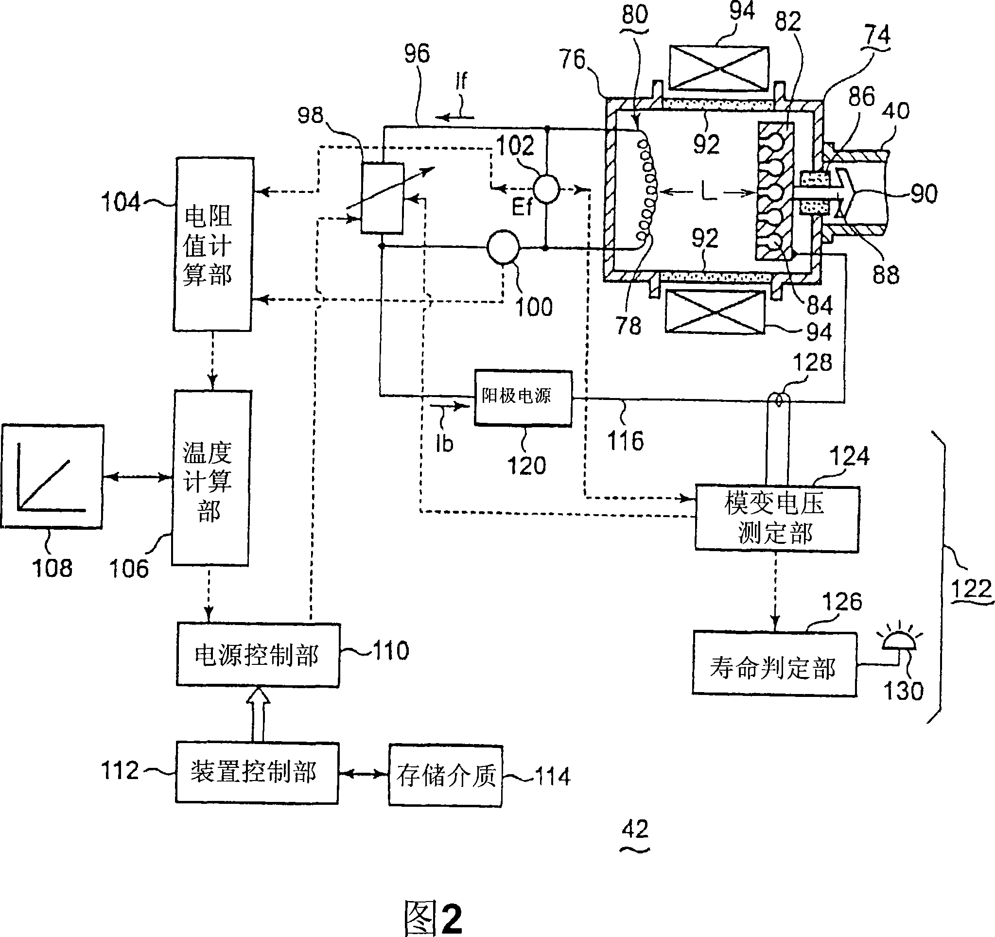
[0044] FIG. 1 is a configuration diagram of an example of a processing device using the microwave generator of the present invention. Figure 2 is a block diagram of the microwave generator. Here, a case where a processing apparatus performs etching using plasma generated by microwaves will be described as an example.

[0045] As shown in the figure, this processing apparatus 2 using plasma has, for example, a side wall and a bottom made of a conductor such as aluminum, and has a cylindrical processing container 4 as a whole. The inside of the processing container 4 is configured as a closed processing space, and plasma is formed in the processing space. The processing contai...


PUM

PropertyMeasurementUnit
diameteraaaaaaaaaa

Abstract

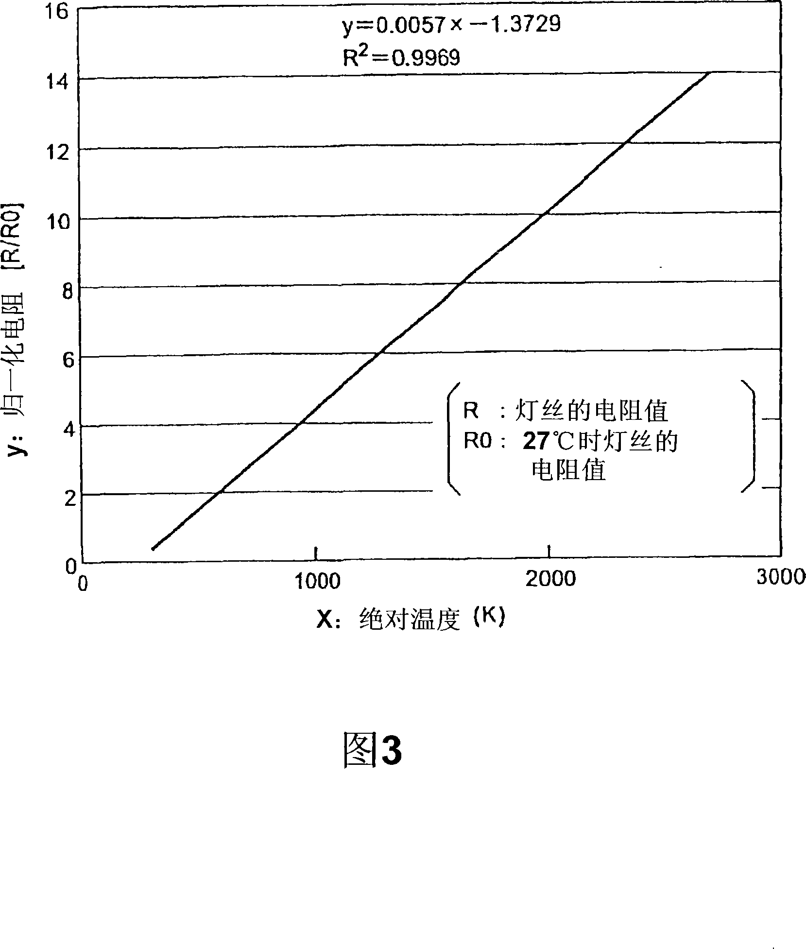
It is possible to increase the service life of a magnetron. There is provided a magnetron service life judgment method. A microwave generation device includes: a magnetron (74) having a cathode (80) containing a filament (78) and an anode (82) containing a hollow resonator (84) arranged to oppose to each other; a filament current measuring unit (100); and an application voltage measuring unit (102) for measuring voltage applied to the filament. According to the current and the voltage obtained by the current measuring unit (100) and the voltage measuring unit (102), a resistance value calculation unit (104) obtains a resistance value of the filament. A temperature calculating unit (106) calculates the filament temperature from the resistance value according to the resistance-temperature dependent characteristic. A filament power source (98) is controlled by a power control unit (110) so that the filament temperature is within a predetermined temperature range. Moreover, the voltage applied to the filament is successively lowered and the voltage applied to the filament when the moding phenomenon occurs is obtained as the moding voltage and the magnetron service life is judged according to the moding voltage.

Description

technical field [0001] The present invention relates to a treatment device for treating the surface of a target object such as a semiconductor wafer using active species activated by plasma, a control method for a magnetron, a method for determining the lifetime of a magnetron, a microwave generator, a magnetron A life determination device, a computer program and a storage medium. Background technique [0002] When forming an integrated circuit of a semiconductor product, various treatments such as film formation, modification, oxidation diffusion, and etching are usually performed on the object to be processed such as a semiconductor wafer. However, due to the high density of semiconductor integrated circuits in recent years, There are more and more processing devices using plasma due to the increasing demand for miniaturization, high miniaturization, thin film, and low temperature processing. In the processing equipment using this plasma, the plasma is used to activate th...

Claims


Application Information

Patent Timeline
Patent Type & Authority Applications(China)
IPC IPC(8): H01J23/34C23C16/511H01J23/04H01L21/3065H05B6/68H05H1/00H05H1/46
CPCH05B6/666H01J37/32201H05B2206/043H01J37/32192H05B6/806H01J23/34H05B6/68H01L21/3065
Inventor 河西繁长田勇辉
Owner TOKYO ELECTRON LTD
Learn More