
LED drive system and backlight module with same

A technology for light-emitting diodes and driving systems, which is applied to electroluminescent light sources, semiconductor devices of light-emitting elements, optics, etc., can solve the problems of complicated manufacturing process of light-emitting diode light rods, inability to detect the temperature of light-emitting diodes, etc., and achieves a long working life. Effect

Inactive Publication Date: 2008-01-16
AU OPTRONICS CORP
View PDF0 Cites 2 Cited by
  • Summary
  • Abstract
  • Description
  • Claims
  • Application Information

AI Technical Summary

Problems solved by technology

That is to say, the known LED drive system cannot be integrated into the above-mentioned LED light stick, which causes the manufacturing process of the above-mentioned LED light stick to be relatively complicated, and the known LED drive system is also prone to heat transfer from the light-emitting diode due to heat conduction. The light rod fell off and the temperature of several LEDs could not be detected

Method used

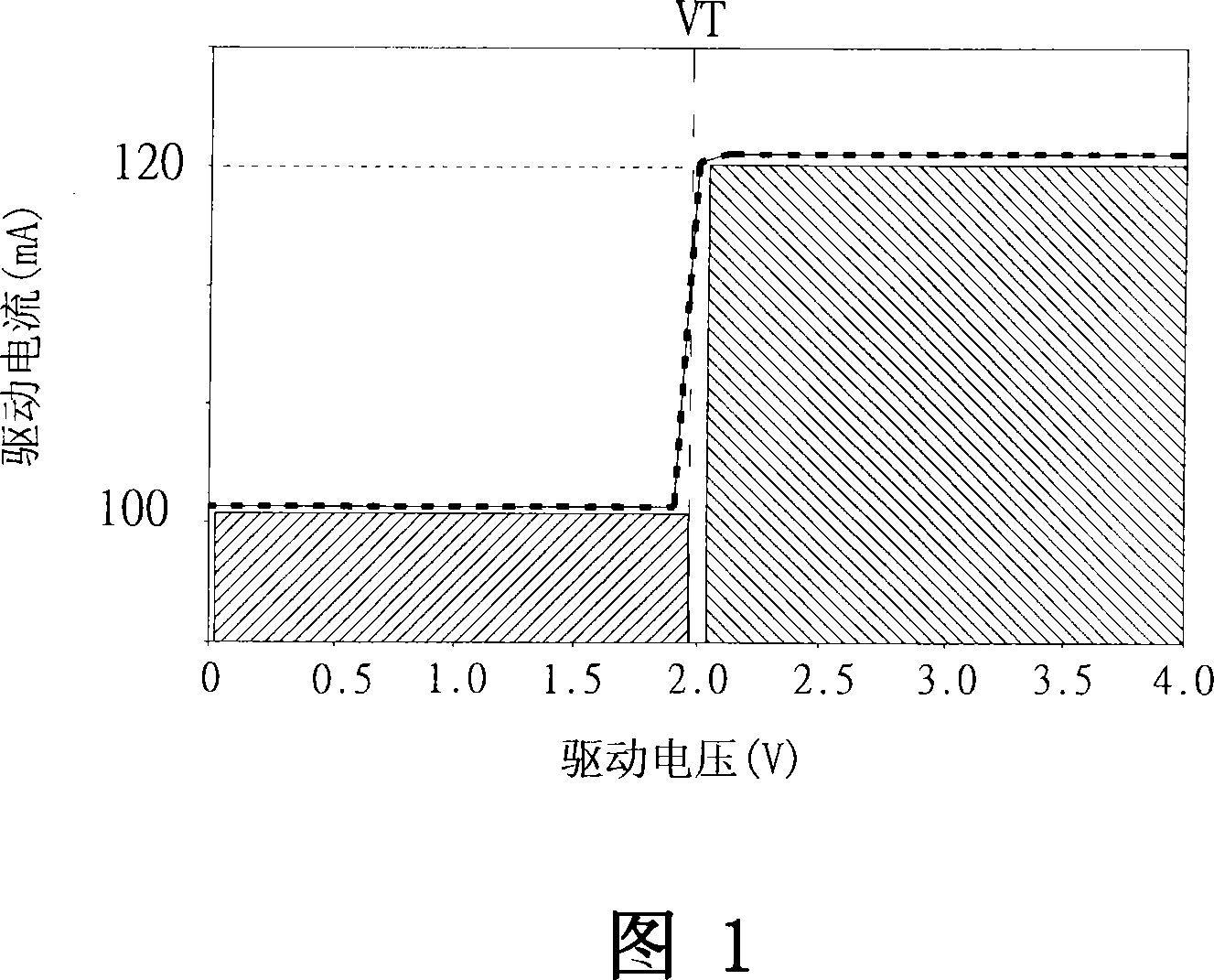
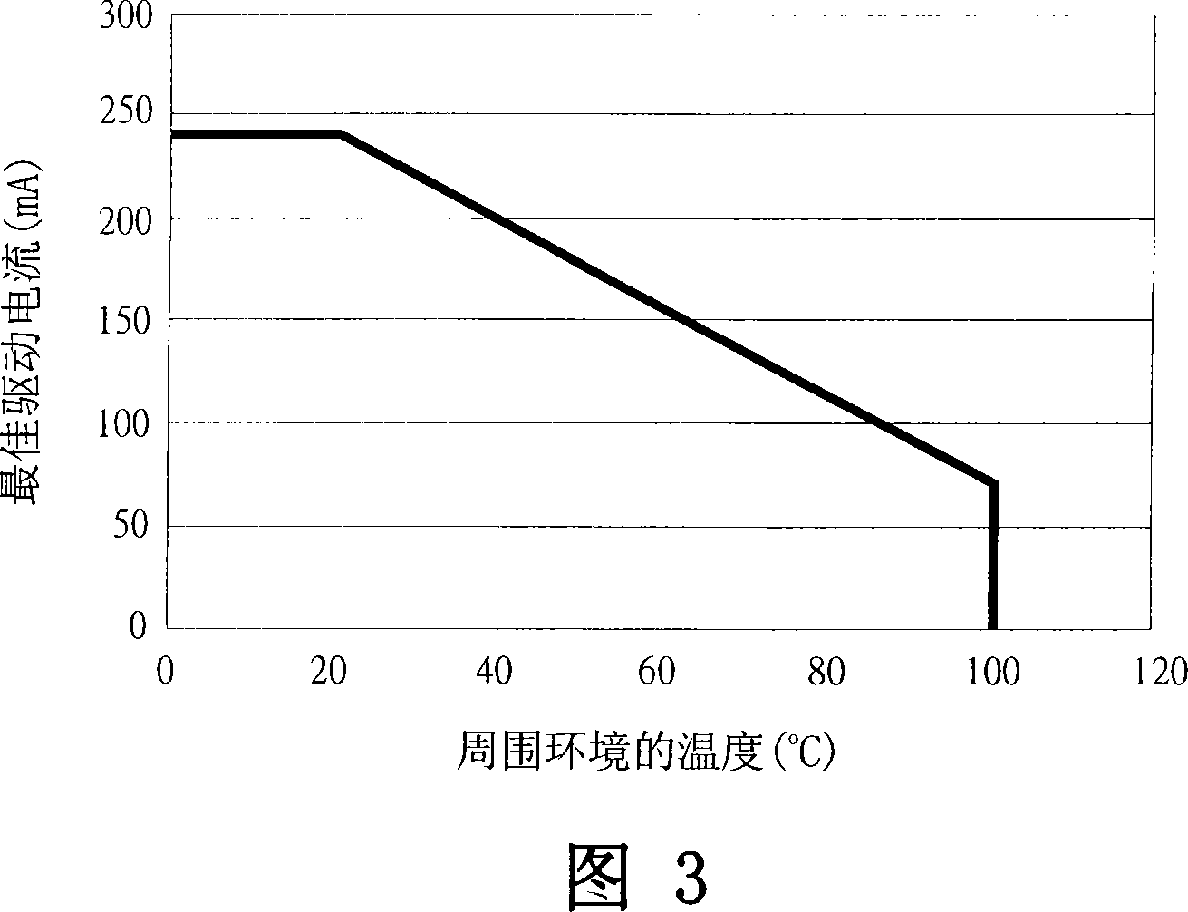

Image

  • LED drive system and backlight module with same
  • LED drive system and backlight module with same
  • LED drive system and backlight module with same

Examples


Embodiment Construction

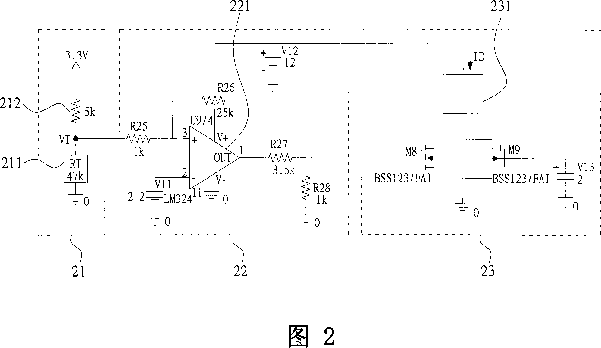
[0047] 2 is a system architecture diagram of an LED driving system according to an embodiment of the present invention, wherein the LED driving system according to an embodiment of the present invention includes: a temperature detection module 21, a hysteresis voltage module electrically connected to the temperature detection module 21 22 and a current limiting module 23 electrically connected to the hysteresis voltage module 22 and a light emitting diode 231 . In addition, an LED driving system according to an embodiment of the present invention is disposed on a circuit board (not shown in the figure), and the above-mentioned LEDs 231 are electrically connected to the circuit board (not shown in the figure).

[0048] On the other hand, the temperature detection module 21 of the LED driving system according to an embodiment of the present invention is connected to the LED 231 and includes a thermoelectric conversion unit 211 , and the hysteresis voltage module 22 includes a hys...


PUM


Abstract

The invention discloses a light emitting diode driving system and a backlight module with the light emitting diode driving system. The light emitting diode driving system is equipped on a circuit board with at least one light emitting diode and includes: a temperature detection module connected with the light emitting diode and including a thermoelectric conversion unit; a hysteresis voltage module electrically connected with the temperature detection module; and a current limiting module electrically connected with the hysteresis voltage module and the light emitting diode. Heat generated by the light emitting diode during work is transferred into the thermoelectric conversion unit and temperature of the thermoelectric conversion unit changes to generate of correspondent voltage; the hysteresis voltage module receives the voltage and generates a hysteresis voltage; and the current limiting module receives the hysteresis voltage and generates a driving current to drive the light emitting diode.

Description

technical field [0001] The present invention relates to a light emitting diode driving system and a backlight module with the light emitting diode driving system, in particular to a device capable of real-time measuring the temperature of a light emitting diode during operation and adjusting and driving the light emitting diode to emit light according to the measured temperature. A light-emitting diode drive system with a driving current value and a backlight module with the light-emitting diode drive system. Background technique [0002] In recent years, with the trend of reducing energy consumption and the thickness of liquid crystal display devices becoming thinner and thinner, backlight modules with several light-emitting diodes as light sources have gradually replaced traditional backlight modules with cold-cathode tubes as light sources, and become the current Mainstream products on the market. However, LEDs have several disadvantages that have yet to be overcome, tha...

Claims


Application Information

Patent Timeline
IPC IPC(8): H05B37/03H05B37/02H05B33/08G02F1/13357F21V19/00F21Y101/02F21Y115/10G02F1/1335H05B44/00
Inventor 许伯骅林志勇张富杰
Owner AU OPTRONICS CORP
Learn More