Radspanner

A technology of wheel tensioner and tensioner, which is applied in the direction of overhead lines, etc.

Active Publication Date: 2010-06-16
理查德伯格电子装置有限及两合公司
View PDF5 Cites 0 Cited by
  • Summary
  • Abstract
  • Description
  • Claims
  • Application Information

AI Technical Summary

Problems solved by technology

However, this can also lead to uneven braking of the subsequent tensioned weight

Method used


Image

  • Radspanner
  • Radspanner
  • Radspanner

Examples


Embodiment Construction

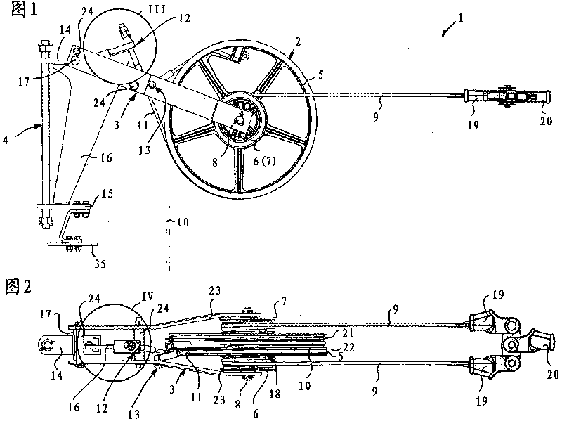
[0047] FIG. 2 shows a top view of the wheel tensioner in FIG. 1 . The tensioning rope 9 is first wound onto the tensioning drum 6 , guided through a passage 18 in a tensioning drum and finally wound onto the tensioning drum 7 . The two cord ends each have a cord attachment 19 . Two rope mounting parts 19 are assembled with a connecting piece 20 . The force transmission to the conductor lines or the carrying cables of the trackless installation takes place via the connecting piece 20 . By means of the tensioning rope 9 wound onto the two tensioning drums 6 , 7 , the subsequent tensioning weight acts uniformly via the tensioning rope 9 on the trolley line or carrier rope. A tilting of the tensioning drum and a possible impediment of the rolling motion associated therewith are thus reliably prevented.

[0048] The brake drum 5 has a slot 21 in the form of a wedge cavity for guiding the weight rope 10 . The weight rope is usually wound multiple times around the brake drum 5 so...


PUM


Abstract

The present invention relates to a wheel tensioner (1) for sliding contact line or bearing rope of a trackless device. The wheel is arranged with a stop with an arrester and a holding device used whenthe sliding contact line or the bearing rope ruptures. Thus, the wheel tensioner comprises a tensioner pulley (2) which is fixed on the trackless bracket or a wall by means of a fixed device (4) andcan swing relative to the trackless bracket or the wall vertically; the tensioner pulley is arranged with a braking roller (5) for installing braking belt or braking rope (11). The braking rope is fixed on the fixed device (4) at the upper fixing point (12). The wheel tensioner also comprises a swing arm (3) which supports the tensioner pulley (2) and is supported on the fixed device (4) by meansof the swing of a rotary bearing (17). The braking rope (11) is fixed on the swing arm (3) at the lower fixing point (13).

Description

technical field [0001] The invention relates to a wheel tensioner. Background technique [0002] The conductor lines and the carrying cables of the trackless system must be constantly tensioned with a certain tensile force, independent of the weather, in order to ensure the correct operation of the trackless system. Tensioning devices with pulley tensioners are used to tension trolley lines and carrying ropes. The wheel tensioners are fastened at regular intervals to a trackless support or wall by means of a fastening device and are part of a holding device supporting the trackless installation. Each wheel tensioner has a tensioning drum, on which a tensioning rope connected to the trackless device is wound. The tensioning of the tensioning rope takes place via a subsequent tensioning weight suspended on the tensioning drum from the weighting rope. The subsequent tensioning weight is designed in such a way that, in particular, temperature-induced length changes of the tra...

Claims


Application Information

Patent Timeline
Patent Type & Authority Patents(China)
IPC IPC(8): B60M1/26
CPCB60M1/26
Inventor H·利加尔
Owner 理查德伯格电子装置有限及两合公司
Why Eureka
Try Eureka