Apparatus for manufacturing taped insulated conductor and method of controlling tape winding tension

A technology for insulated wire cores and manufacturing devices, which is applied in rope-making auxiliary devices, cable/conductor manufacturing, conductor/cable insulation, etc., can solve the problems of easy change, unstable tension, large contact area, etc., and eliminate breakage , to eliminate the effects of changes

Inactive Publication Date: 2008-01-09
HIRAKAWA HEWTECH +1
View PDF5 Cites 9 Cited by
  • Summary
  • Abstract
  • Description
  • Claims
  • Application Information

AI Technical Summary

Problems solved by technology

(1) Since the tape reel is floated by air, and the tape is supplied by rotating the tape reel by the rotation of the reel, the tension of the tape supply is likely to vary depending on the amount of tape wound on the tape reel.
(2) The belt tension changes due to the unbalanced rotation speed of the motors 57 and 513, the winding amount changes, and the winding shape is difficult to stabilize
(3) The tape length from the tape supply part to the tape pusher 519 becomes longer, and the tape tension of the tape supply part and the tape tension of the tape winding part are not integrated, so it is easy to cause wind pressure when the tape is wound. breakage of the belt
(4) Although the winding tension of the tape is generated by contact with the guide hole 516, the tape cover 517, and the tape winding guide 518, it is easily changed due to the relatively large contact area and the rotation speed of the flywheel 510.
(5) Due to the above (1) and (2), the tension of the tape caused by the supply and winding of the tape is unstable, and the winding of the tape tends to become unstable, so the shape of the winding becomes uneven, and it is easy to breakage of the belt
(6) Since the tape pulled out from the tape reel is long from the tape reel to the tape winding place (tape pusher 519), the tape tension tends to change due to the wind pressure caused by the rotation of the flywheel 510.
However, since the tape feed tension is controlled (increased or decreased) based on a predetermined torque, when the tape winding amount changes, large variations in the tape feed tension occur.

Method used

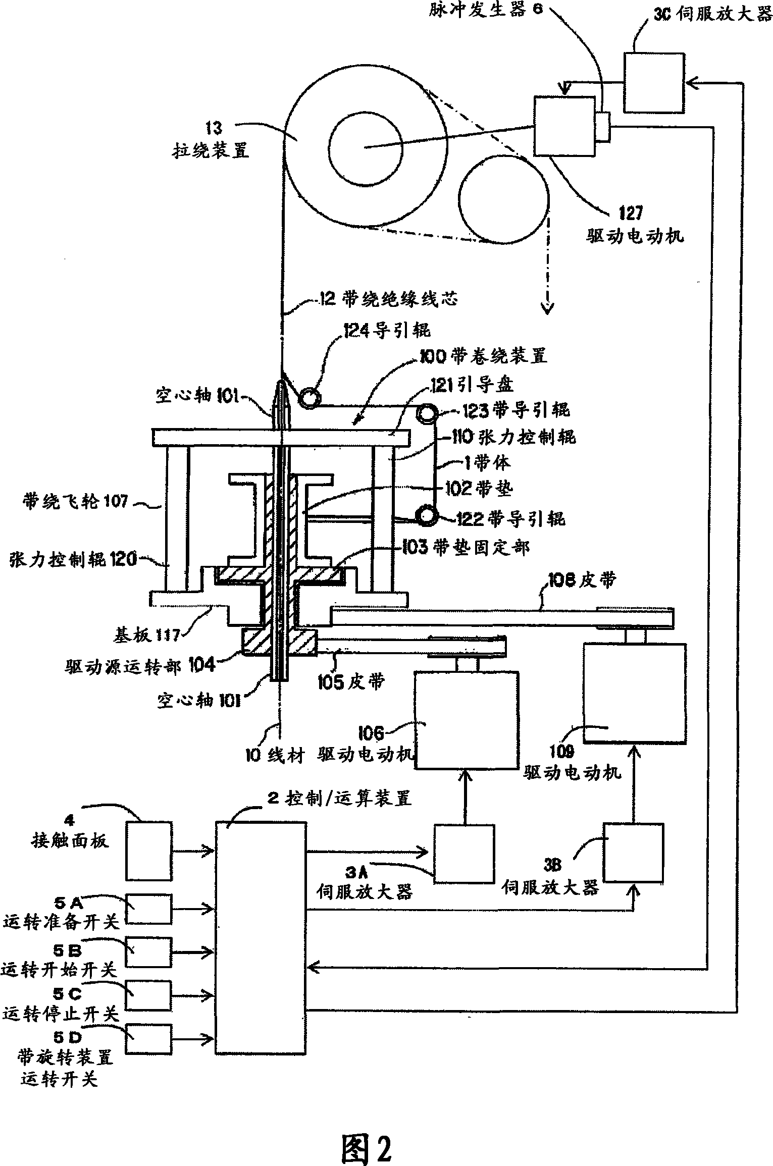
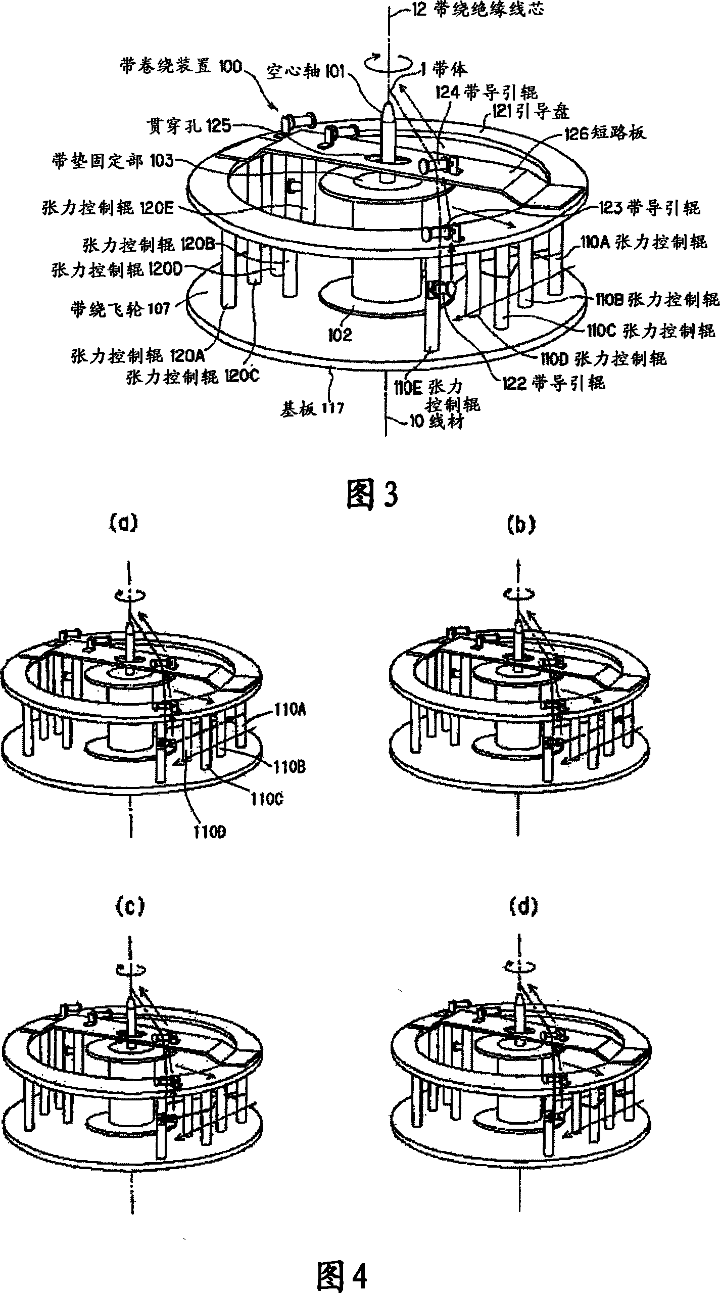

Image

  • Apparatus for manufacturing taped insulated conductor and method of controlling tape winding tension
  • Apparatus for manufacturing taped insulated conductor and method of controlling tape winding tension
  • Apparatus for manufacturing taped insulated conductor and method of controlling tape winding tension

Examples


Embodiment

[0083] FIG. 6 is a graph showing the relationship between the length of the belt body 1 (belt length), the shaft torque constant value, and the belt pull-out tension. Utilize the touch panel 4, as the initial torque setting of the driving motor 106, as a value balanced with the zero tension of the gradually decreasing value, the input shaft torque constant value is 100.00 and the belt length of the belt body 1 is 900m. In addition, as the setting of the rotational speed value of the drive motor 109, the rotational speed value of the tape winding flywheel 107 is inputted as 1500 rpm, and 10000 m is inputted as the length value of the winding rod. In addition, the product winding pitch setting value of 6.6mm is also input. In addition, 200m and 60.00 are respectively input as the strip length value and the end torque value of the first stage of the drive motor 106 as the section of the belt body 1 of the first stage, and the strip length value is used as the section of the belt ...


PUM

PropertyMeasurementUnit
foaming ratioaaaaaaaaaa
porosityaaaaaaaaaa
lengthaaaaaaaaaa

Abstract

An apparatus for manufacturing a taped insulated conductor and a method of controlling a tape winding tension. The apparatus comprises a wire material feeder feeding a wire material, a tape winder winding a tape body on the wire material fed from the wire material feeder, and a receiving device receiving the wire material on which the tape body is wound by the tape winder. A rotating shaft torque is controlled to a prescribed torque by rotatingly driving a tape pad fixing part by a torque gradually decreasing control without relying on the number of the windings of the tape body. Thus, the delivery tension of the tape body can be set to a specified prescribed value.

Description

technical field [0001] The present invention relates to a tape-wound insulated wire manufacturing device and a method for controlling tape winding tension, in particular to a tape-wound insulated wire manufacturing device for forming an insulator on the outer periphery of a conductor by winding an extremely thin porous tape A tape winding tension control method that stabilizes the winding operation by maintaining a constant tape tension when winding an extremely thin porous tape around the outer circumference of a conductor. Background technique [0002] With the development of an advanced information society in recent years, there is an increasing demand for higher transmission speed and higher transmission accuracy in information communication equipment and test / inspection devices for semiconductor elements used in the equipment. Accordingly, the coaxial cables and coaxial cords used in such devices and devices are also required to increase the transmission speed and impro...

Claims


Application Information

Patent Timeline
Patent Type & Authority Applications(China)
IPC IPC(8): H01B13/08
CPCH01B13/0866D07B7/14B65H81/02H01B13/00
Inventor 齐藤寿朗南城光夫
Owner HIRAKAWA HEWTECH
Why Eureka
Try Eureka