
Rotating blade vehicle type fluid machine

A fluid machine and rotor blade technology, applied in liquid fuel engines, swing piston machines, engines, etc., can solve the problems of high construction and maintenance costs, unmarketable, bulky, etc., and achieve a short construction period, a wide range of wind speeds, large space effect

Inactive Publication Date: 2008-01-09
陈崟
View PDF0 Cites 22 Cited by
  • Summary
  • Abstract
  • Description
  • Claims
  • Application Information

AI Technical Summary

Problems solved by technology

The development of tidal energy is currently building dams in bays, using the sea potential difference of rising and falling tides to drive low-head inertial turbines to convert them into mechanical energy. The bays where dams can be built are limited, and the tidal energy in wide sea areas is only a small part. Moreover, the inertial turbine generator is bulky underwater, and the cost of construction, installation and maintenance is high.
The fluid machinery for tidal currents and ocean currents in wide sea areas is currently mainly inertial turbines and propeller turbines with horizontal axis fans, and they have not been marketed.

Method used


Image

  • Rotating blade vehicle type fluid machine
  • Rotating blade vehicle type fluid machine
  • Rotating blade vehicle type fluid machine

Examples


Embodiment approach

[0059] Mode 1: A power station consisting of underwater hydraulic machines, chain pumps, pipelines, accumulators, filters, and hydroelectric generator sets.

[0060] 1. Hydraulic machine

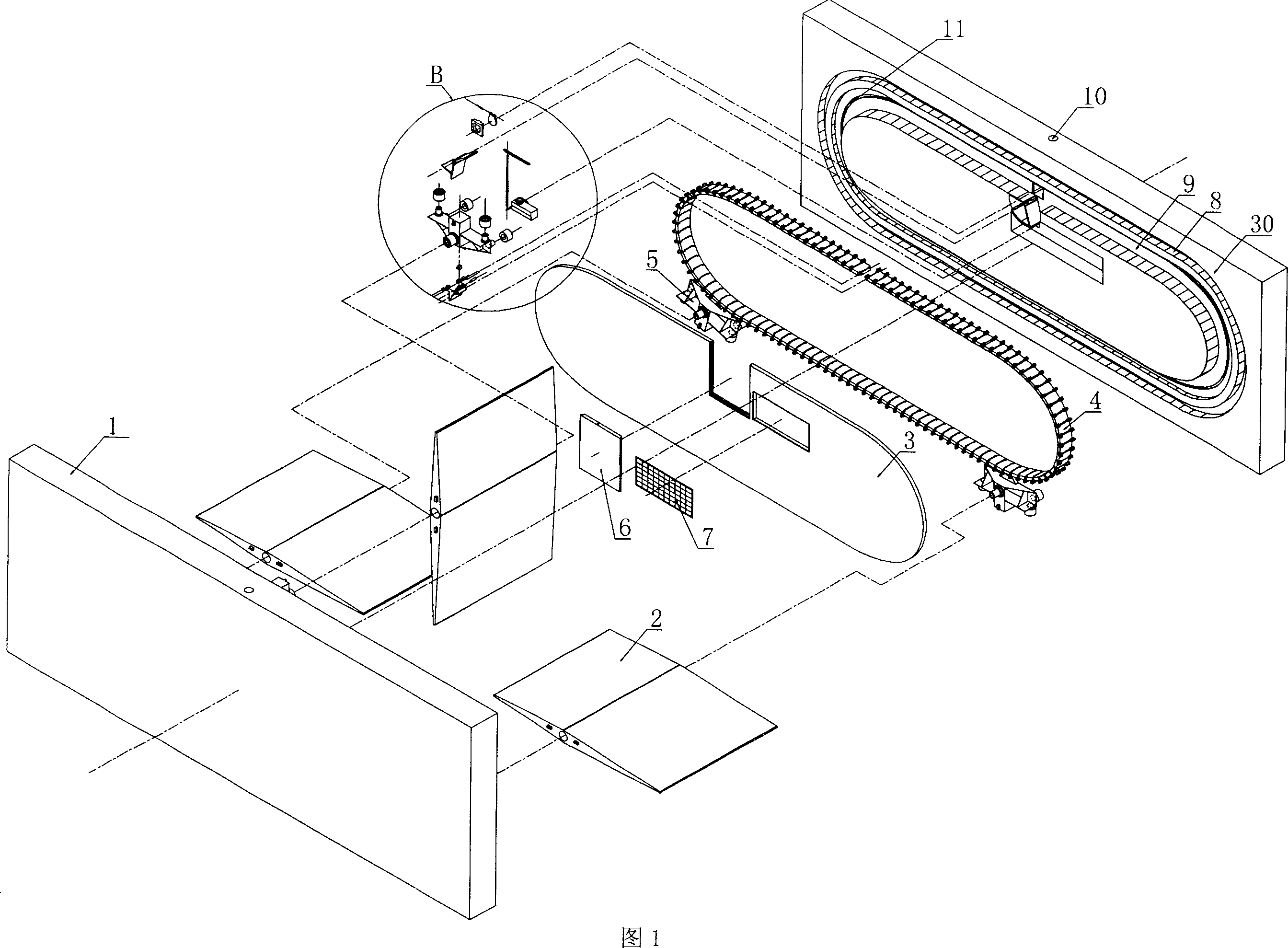
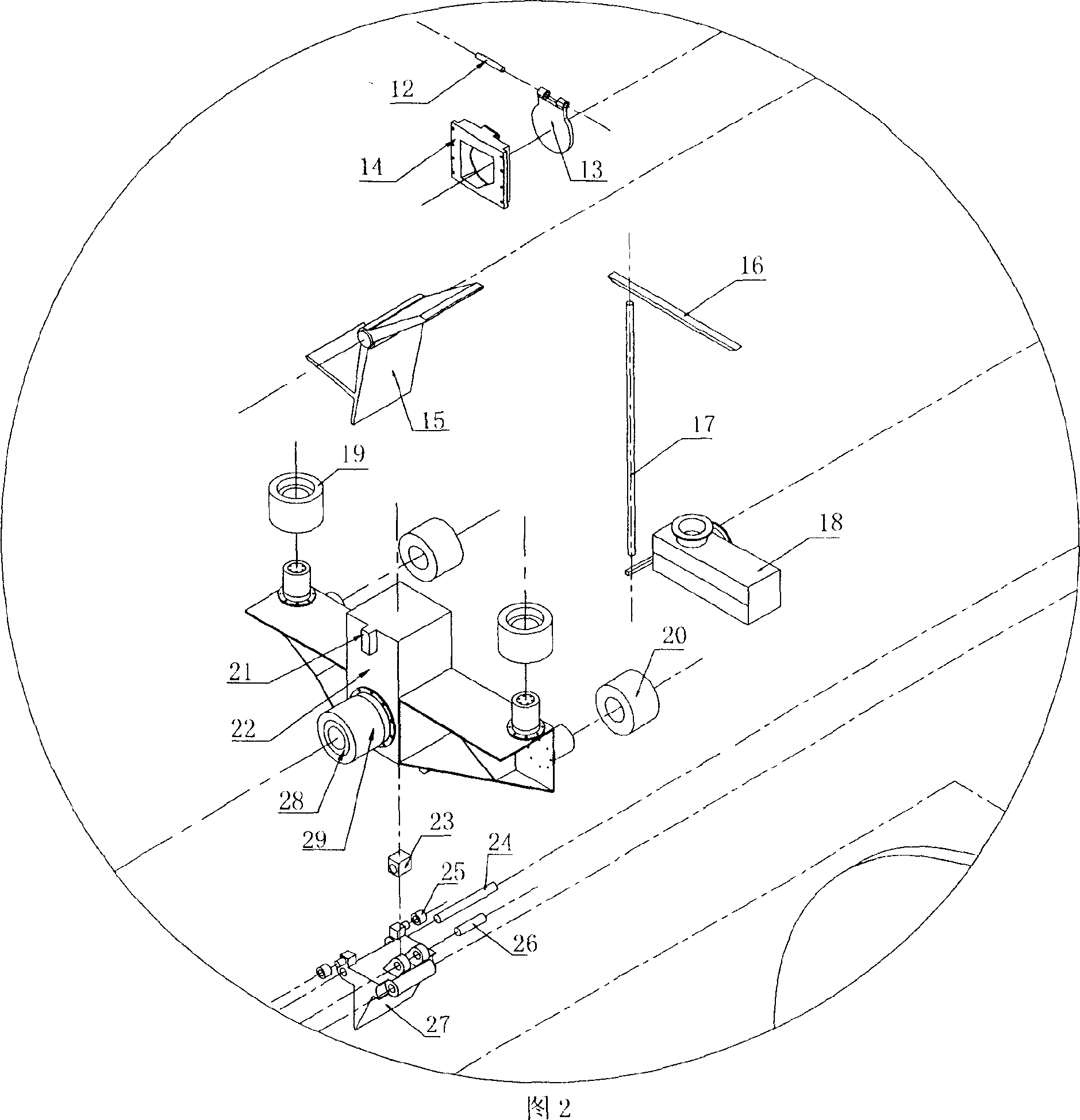
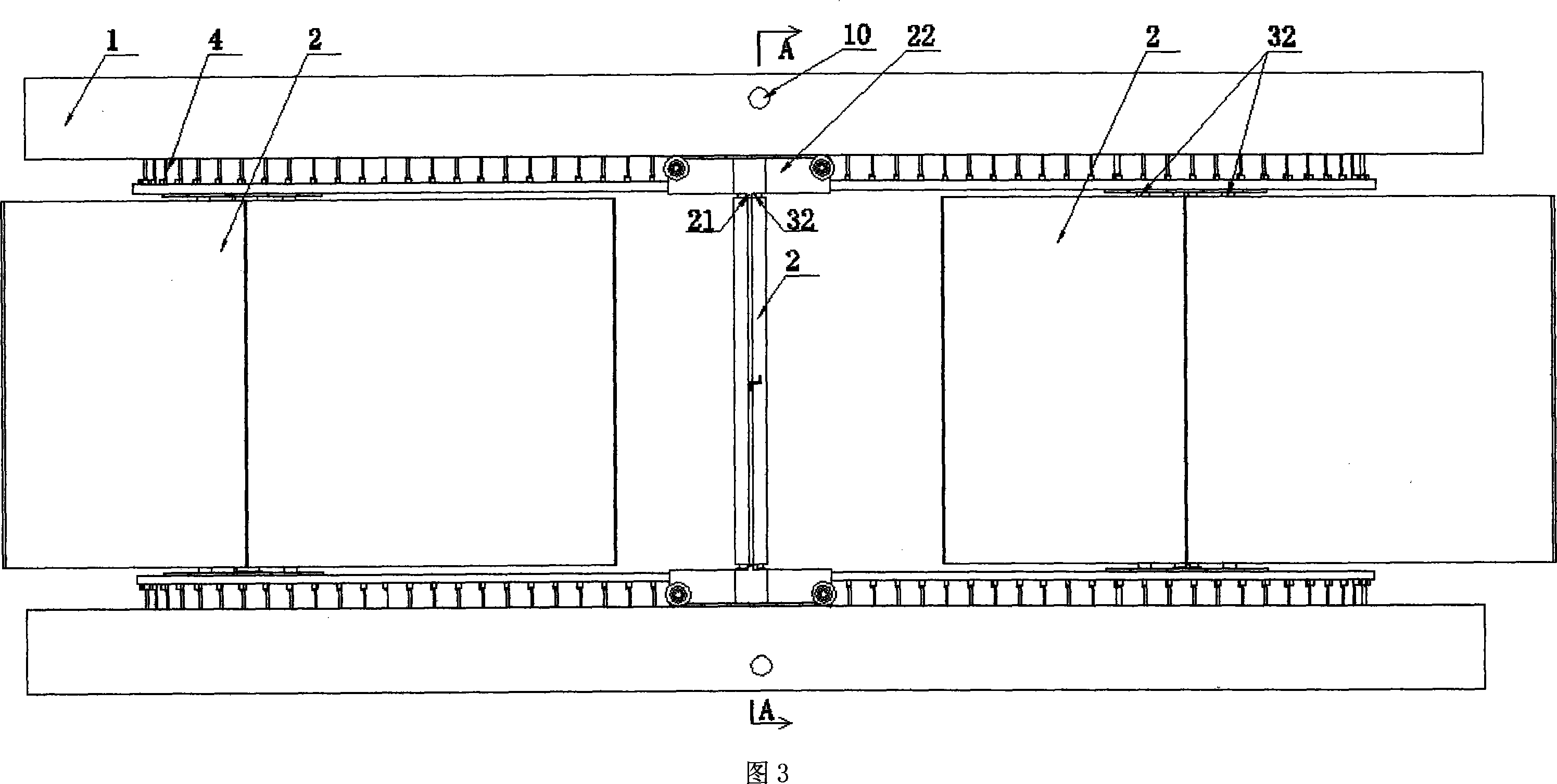
[0061] As shown in Figure 1-7: Fix the left-right symmetrical frame (1) on the underwater foundation, and the underwater foundation is fixed on the bottom of the water or anchored in the water. The left-right symmetrical frame has the rotary leaf car A track (8) and the rotary leaf car B track (30). Composition, the length of the straight line section of the A track (8) of the rotary vane car is between 3 / 2πR to 2πR (R is the radius of the arc section), and the straight line section of the track is parallel to the fluid direction in the fluid field where it is located. One side has three rotating leaf cars (5) all on the track. The rotary vane car is made up of the rotary vane vehicle frame (22), the rotary vane vehicle B roller (19), the rotary vane vehicle A roller (20), and the rotary van...


PUM


Abstract

This invention is rotating blade car type fluid power generator. The chain connects to three groups of rotating blade cars. Rotating blades are evenly distributed on circulate track. Two straight tracks and two half circular arc tracks are connected to form circulating track. Under the effect of fluid, rotating blade of rotating blade car is vertical to fluid flowing direction at the straight segment of track. Thus, fluid active force is strong. At another straight segment, under the effect of fluid, rotating blade of rotating blade car is parallel to fluid flowing direction. Thus, fluid active force is little. The three groups of rotating blade cars and rotating blades undertake circulating operation along track. The chain transfers power to power generator through driving train. The flow power driving train, which is applied underground, is composed of chain pump, pipe, accumulator and water turbine. It makes power generator can be assembled on water surface. The resistance type wind power machine is driven by chain.

Description

Technical field: [0001] The rotary vane type fluid machine belongs to fluid machinery and is used for the extraction of wind energy and hydrokinetic energy (rivers, tides, ocean currents). Background technique: [0002] The wind and water currents on Earth contain a lot of energy. At present, the utilization of wind energy is mainly the horizontal axis propeller fan, whose blades can only use the mechanical energy generated by the lift force in the kinetic energy of the fluid, and the primary cut-off energy is limited. The water energy in rivers is now dammed and intercepted to use the potential energy of water to drive the water turbine to convert it into mechanical energy. The period of building dams on rivers is long and the project is huge. It requires extensive geological and ecological investigation and research, which will affect the surrounding ecological environment; In agriculture, water vehicles are used to extract the kinetic energy of water and convert it into ...

Claims


Application Information

Patent Timeline
Patent Type & Authority Applications(China)
IPC IPC(8): F03D5/02F03D9/00F03B9/00F03B17/06F03B13/06F04C9/00
CPCF03D5/02Y02E60/17F03B17/068Y02E10/28Y02E10/70F03D5/04Y02B10/30Y02E10/30Y02E60/16
Inventor 陈崟
Owner 陈崟
Learn More