Polarization maintaining optical fiber with microstructure
A polarization-maintaining optical fiber and microstructure technology, applied in polarized optical fiber, cladding optical fiber, optical waveguide light guide, etc., can solve problems such as inability to transmit optical fiber, and achieve the effect of rich dispersion characteristics and large core area
- Summary
- Abstract
- Description
- Claims
- Application Information
AI Technical Summary
Problems solved by technology
Method used
Image
Examples
Embodiment 1
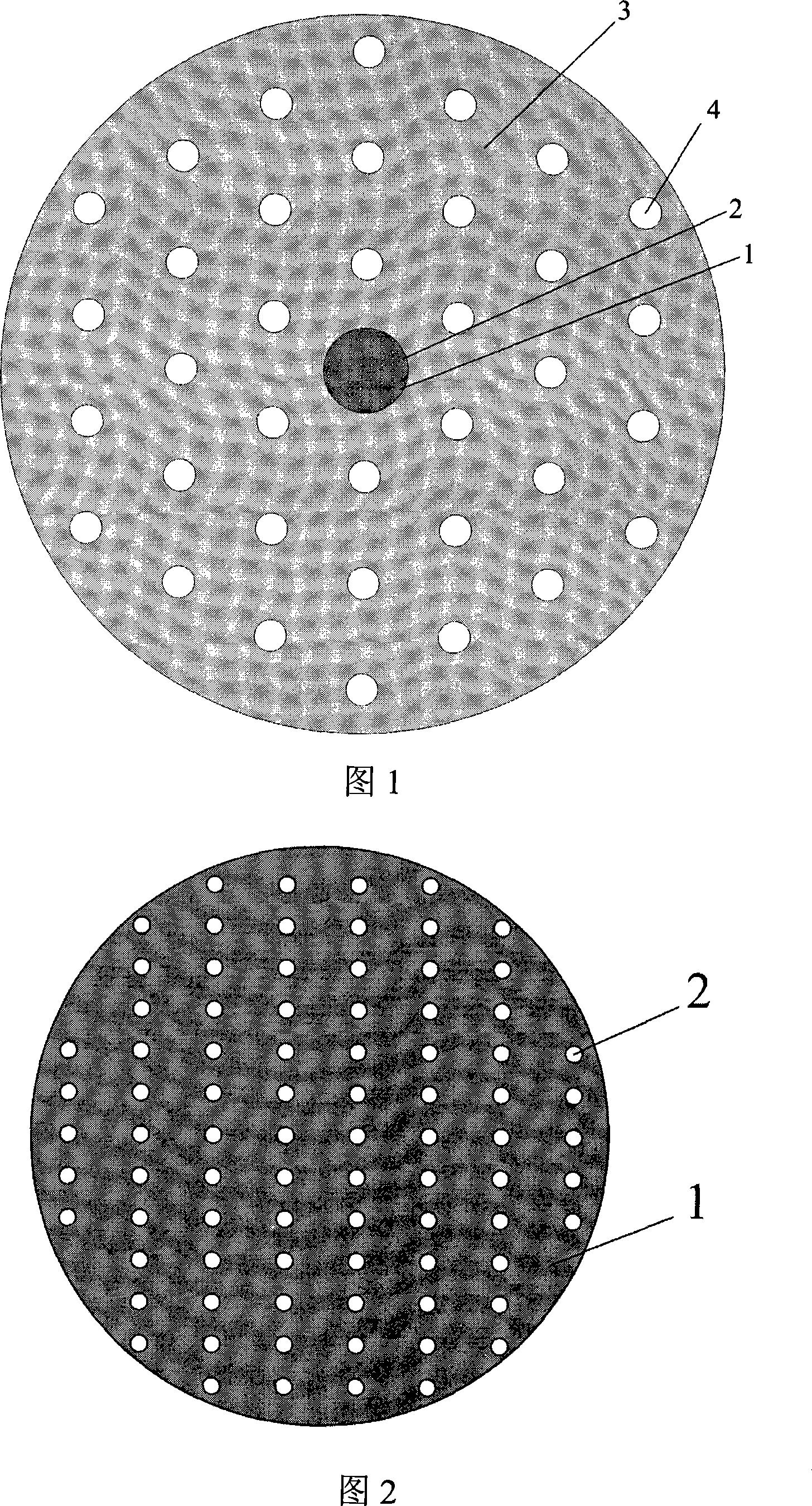
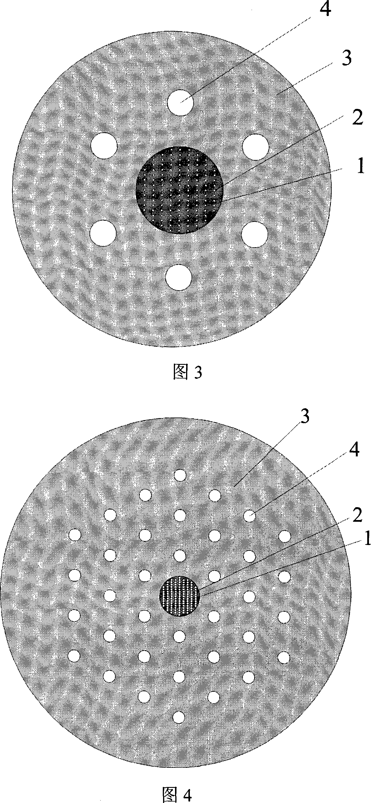
[0038] FIG. 1 is a schematic cross-sectional view of a microstructure core fiber with high birefringence and large mode field characteristics, and FIG. 2 is an enlarged schematic view of the core structure of the fiber. The fiber core of the optical fiber is composed of a dielectric material 1 and air holes 2 in the core area, wherein the air holes are arranged in a rectangular shape, so that the fiber core has second-order symmetry. The holes 4 in the cladding region are also air holes. The diameter of the fiber core is 7.44 μm, the vertical spacing of the air holes 2 in the core area is 0.93 μm, and the horizontal spacing is 0.537 μm, that is, when the light wavelength is 1.55 μm, the corresponding spacing is 0.6 and 0.35 light wavelengths respectively. The diameter of the air hole is taken as 0.242 μm. The pitch of the air holes in the cladding is taken as 9.3 μm, and the diameter of the air holes is taken as 3.72 μm. Pure quartz and doped quartz (such as doped GeO 2 ) a...
Embodiment 2
[0040] Fig. 3 is a schematic cross-sectional view of a microstructure core fiber with large mode field and single polarization characteristics. The fiber core of the optical fiber is composed of a dielectric material 1 and air holes 2 in the core area, wherein the air holes are arranged in a rectangular shape, so that the fiber core has second-order symmetry. The holes 4 in the cladding region are also air holes. The diameter of the core area is 10.54 μm, the longitudinal spacing of the air holes 2 in the fiber core area is 1.054 μm, and the lateral spacing is 0.609 μm, that is, when the light wavelength is 1.55 μm, the corresponding spacing is 0.68 and 0.39 light wavelengths respectively. The diameter of the air hole is taken as 0.274 μm. The distance between the air holes in the cladding is 10.54 μm, and the diameter of the air holes is taken as 4.216 μm. Pure quartz and doped quartz (such as doped GeO 2 ) as the dielectric material 1 of the fiber cladding dielectric mate...
Embodiment 3
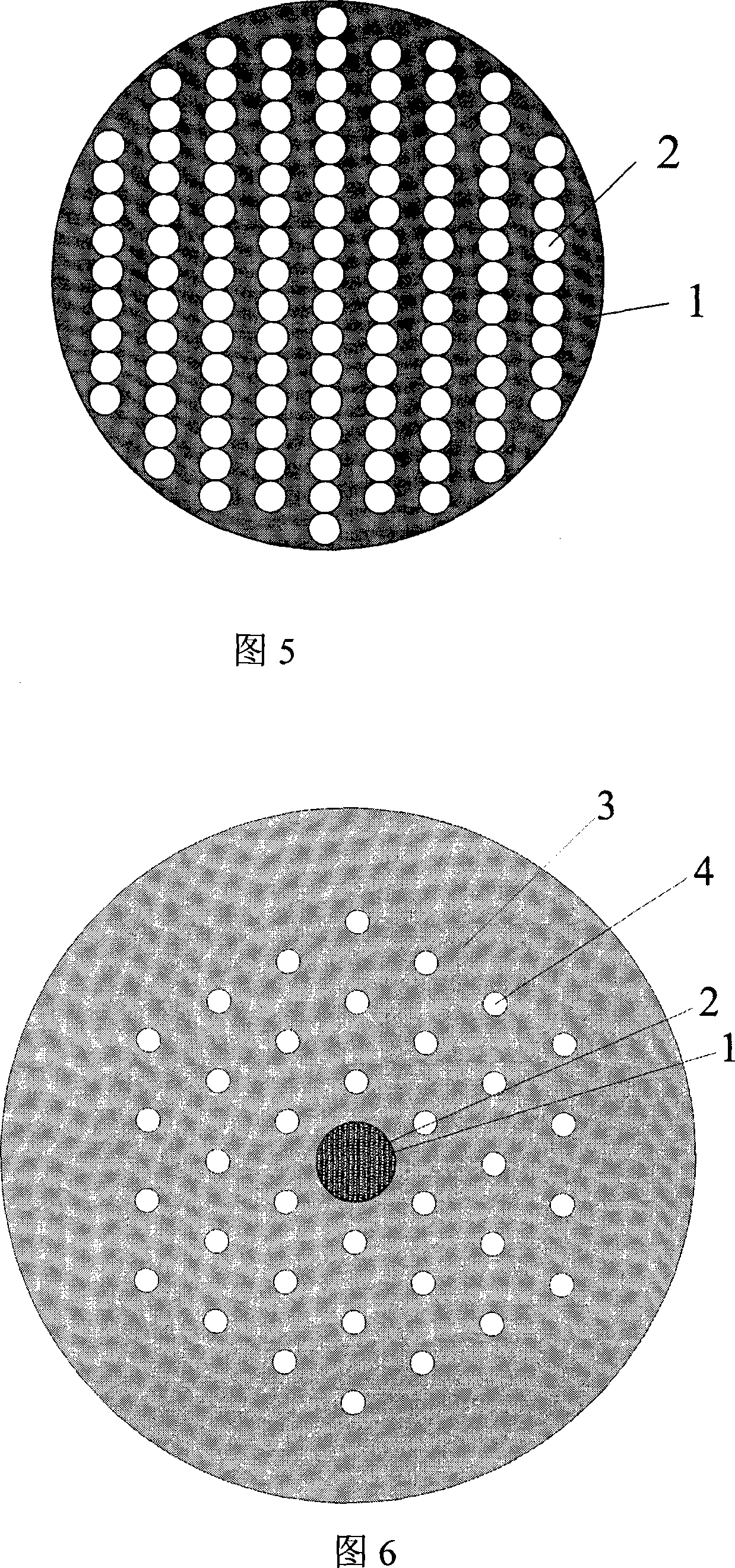
[0042] FIG. 4 is a schematic cross-sectional view of a microstructured solid-core optical fiber with high birefringence and large mode field characteristics, and FIG. 5 is an enlarged schematic view of the fiber core. The core of the optical fiber is composed of a dielectric material 1 in the core area and another solid material filled into the holes 2, wherein the holes 2 are arranged in a rectangular shape, but the longitudinal holes are connected to each other, so that the The ratio of the total area of the holes to the total area of the core is relatively large, so that the core has a high birefringence. The holes 4 in the cladding region are air holes. The diameter of the core area is 9.3 μm, the longitudinal spacing of the holes in the core area is 0.93 μm, and the lateral spacing is 0.537 μm, that is, when the light wavelength is 1.55 μm, the corresponding spacing is 0.6 and 0.35 light wavelengths respectively. The diameter of the hole is taken as 0.537 μm. The pi...
PUM
| Property | Measurement | Unit |
|---|---|---|
| diameter | aaaaa | aaaaa |
| refraction | aaaaa | aaaaa |
Abstract
Description
Claims
Application Information
 - R&D
- Intellectual Property
- Life Sciences
- Materials
- Tech Scout
- Unparalleled Data Quality
- Higher Quality Content
- 60% Fewer Hallucinations
Browse by: Latest US Patents, China's latest patents, Technical Efficacy Thesaurus, Application Domain, Technology Topic, Popular Technical Reports.
© 2025 PatSnap. All rights reserved.Legal|Privacy policy|Modern Slavery Act Transparency Statement|Sitemap|About US| Contact US: help@patsnap.com


