A flow guiding polarized plate of fuel battery
A diversion plate and fuel cell technology, applied in the direction of fuel cells, fuel cell parts, battery electrodes, etc., can solve the problems of large effective area and difficult arrangement of plates, and achieve increased power density and active area , Good drainage effect
- Summary
- Abstract
- Description
- Claims
- Application Information
AI Technical Summary
Problems solved by technology
Method used
Image
Examples
Embodiment 1
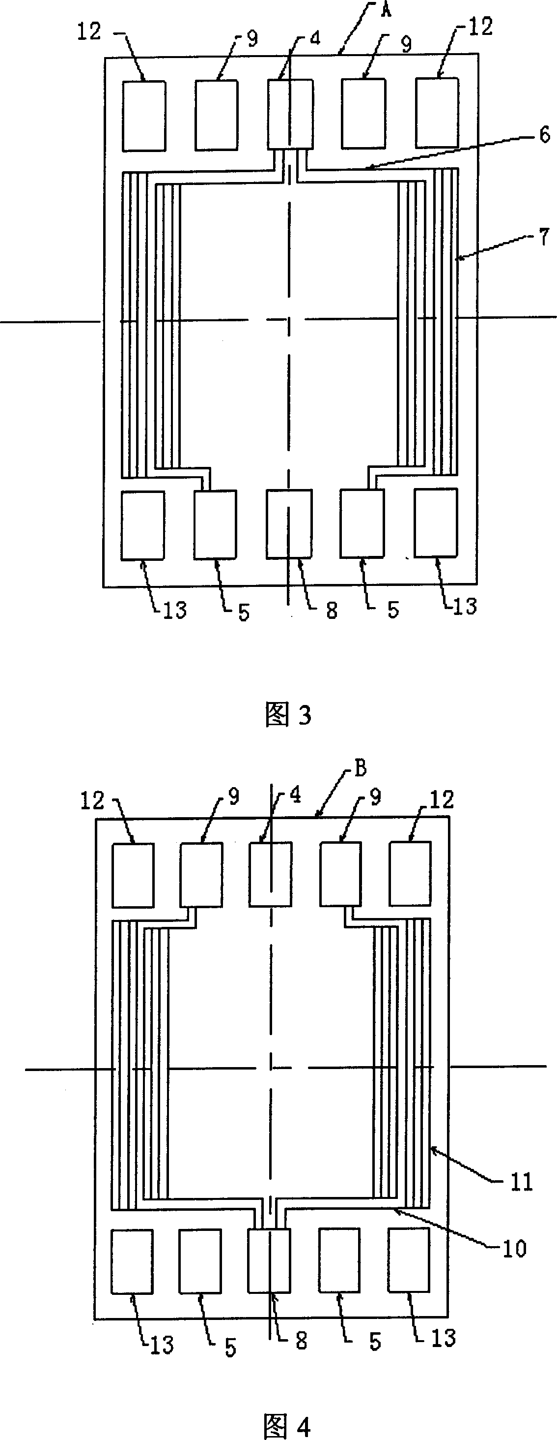
[0043] As shown in Fig. 3 and Fig. 4, a flow guide plate of a fuel cell is a flow guide bipolar plate. The hydrogen flow channel plate B is composed of an intermediate cooling fluid interlayer. The air guide channel plate is provided with a single hole 4 inlets and a double hole 5 air outlet fluid holes. The air inlet fluid holes are divided into four guide air flow grooves 6 , each of the four air-guiding channels divides into four branch air-flow channels 7 in a parallel straight-line shape, and the branch air-guiding channels 7 are brought together to the four air-guiding channels at the other end, and the four air-guiding channels are respectively Enter the air-out fluid hole 5 of the guide bipolar plate near the middle position; the hydrogen-guiding air flow channel plate is provided with single-hole 8 inlet and double-hole 9 outlet hydrogen fluid holes, and the fluid holes for hydrogen inlet are divided into four The hydrogen flow groove 10, the four hydrogen flow groove...
Embodiment 2
[0046] As shown in Figure 5, a flow guide plate of a fuel cell is a flow guide bipolar plate, and the flow guide bipolar plate is composed of a front guide air channel plate and a reverse hydrogen guide air flow channel plate 1. The middle guide cooling fluid interlayer is composed of, and the described air guide slot plate is provided with a single hole 14 into and a double hole 15 out of the air fluid hole, and the air inlet fluid hole is divided into six guide air flow slots, and the six guide air flow slots Each of the grooves is divided into four branch air flow grooves in a parallel straight-line shape, and the branch air flow grooves are collected into the six air flow grooves at the other end, and the six air flow grooves enter the flow diversion bipolar plate respectively. In the air-out fluid hole on the side; the hydrogen-guiding air flow slot plate is provided with a single-hole inlet and a double-hole hydrogen outlet fluid hole, and the hydrogen-inlet fluid hole is...
Embodiment 3
[0049] Please refer to Fig. 3, 4, and 5, a kind of flow guide plate of fuel cell, the flow guide plate is a flow guide bipolar plate. It is composed of a hydrogen guide air flow slot plate and an intermediate cooling fluid interlayer. The air guide slot plate is provided with a single-hole air inlet and four-hole air outlet fluid holes. The air inlet fluid holes are divided into twenty air guide flow slots. Each of the twenty air-guiding channels is divided into two branch air-guiding channels in a parallel straight-line shape. The launder enters the fluid holes for air outlet respectively; the hydrogen-conducting air-flow channel plate is provided with single-hole inlet and four-hole hydrogen-out fluid holes, and twenty hydrogen-conducting airflow grooves are separated from the fluid holes for hydrogen inlet. Each of the twenty hydrogen-conducting air flow grooves divides into two branch hydrogen-conducting air flow grooves in a parallel straight-line shape. The grooves ente...
PUM
 Abstract
Description
Claims
Application Information
 - R&D
- Intellectual Property
- Life Sciences
- Materials
- Tech Scout
- Unparalleled Data Quality
- Higher Quality Content
- 60% Fewer Hallucinations
Browse by: Latest US Patents, China's latest patents, Technical Efficacy Thesaurus, Application Domain, Technology Topic, Popular Technical Reports.
© 2025 PatSnap. All rights reserved.Legal|Privacy policy|Modern Slavery Act Transparency Statement|Sitemap|About US| Contact US: help@patsnap.com


