
Technique and device for catalyzing biomass fast thermal cracking by high temperature ironic liquid

A technology of ionic liquid and pyrolysis, which is applied in the field of high-temperature ionic liquid catalyzed rapid pyrolysis of biomass and equipment, to achieve rapid pyrolysis process, low investment cost and stable temperature field

Inactive Publication Date: 2010-05-26
ZHEJIANG UNIV OF TECH
View PDF5 Cites 0 Cited by
  • Summary
  • Abstract
  • Description
  • Claims
  • Application Information

AI Technical Summary

Problems solved by technology

At present, domestic and foreign biomass rapid pyrolysis technologies use sand, quartz sand or ceramic balls as heat carriers for biomass pyrolysis, and there is no report on the use of high-temperature ionic liquids as biomass rapid pyrolysis heat carriers

Method used


Image

  • Technique and device for catalyzing biomass fast thermal cracking by high temperature ironic liquid
  • Technique and device for catalyzing biomass fast thermal cracking by high temperature ironic liquid
  • Technique and device for catalyzing biomass fast thermal cracking by high temperature ironic liquid

Examples


Embodiment 1

[0025] 300g of molten salt NaNO 3 Place in a 500ml three-neck round bottom flask, heat with an external electric heating mantle, and constantly fill the inside of the round bottom flask with N 2 , connect two condenser tubes in series at the upper end of the round bottom flask, and use water close to 0°C to condense, and connect a 125ml round bottom flask at the lower end of the condenser tube. When the heating temperature in the round bottom flask rises to 307°C, NaNO 3 It starts to melt and becomes liquid. When the temperature in the round-bottomed flask rises to 335°C, continuously and evenly add 100 g of sawdust with a particle diameter of about 1.5 mm into the round-bottomed flask through a modified grinding port of the round-bottomed flask. When the sawdust particles are in contact with the high-temperature molten salt, the sawdust particles are cracked within less than 1 second, and oil droplets are enriched on the tube wall of the condenser tube, which will finally be...

Embodiment 2

[0027] Molten salt KNO 3 、NaNO 2 and NaNO 3 Be 53%: 40%: 7% according to mass ratio and be mixed with mixed molten salt, the mixed molten salt of 300g is placed in the three-neck round-bottomed flask of 500ml, external electric heating mantle heating, constantly fill into N to the inside of round-bottomed flask. 2 , connect two condenser tubes in series at the upper end of the round bottom flask, and use water close to 0°C to condense, and connect a 125ml round bottom flask at the lower end of the condenser tube. When the heating temperature in the round-bottom flask rises to 142°C, the mixed molten salt begins to melt and assumes a liquid state. Continuously and uniformly add 100g of wood chips with a particle diameter of about 1.5mm into the bottom flask. After the wood chips contact with the high-temperature molten salt, the wood chips will be cracked within <1s, and then enriched on the wall of the condenser tube. There were oily drops which eventually collected in a 12...


PUM

PropertyMeasurementUnit
cracking temperatureaaaaaaaaaa

Abstract

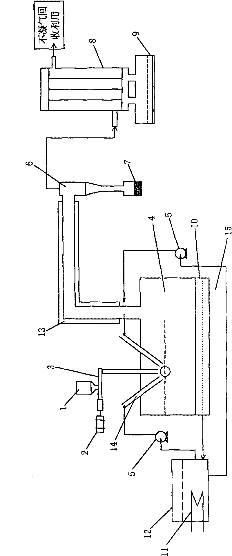
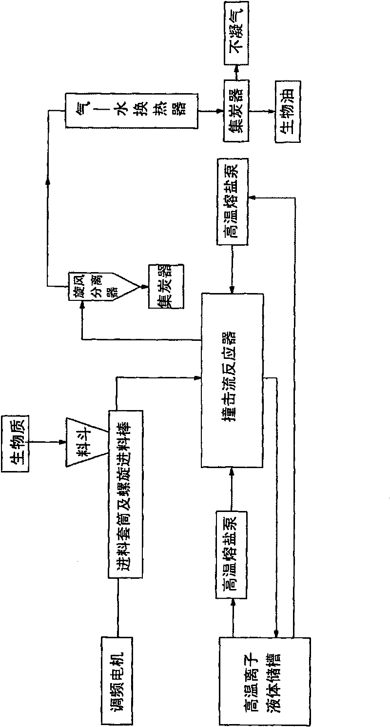
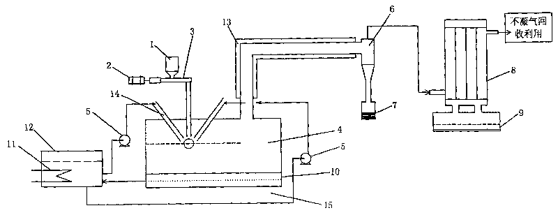
The inventio relates to a process of hihg- temperature ionic liquid catalytic biomass through fast thermal cracking and used device. It comprises following steps: feeding biomass particles to impingerthrough screw feeder, feeding high- temperature ionic liquid into impinger by using high- temperature fused salt pump, the biomass particles is cracked fast under high- temperature ionic liquid action; feeding the cracking gas into cyclone filter and condensing it into biological oil, collecting uncondensed gas and reusing it. The device comprises screw feeder, adjustable speed motorm, high temperature fused pump, impinger, cyclone filter, char collecting device, gas- water exchanger, oil collector, main electric heater, auxiliary electric heater, and high temperature ionic liquid storage tank. The invention is characterized by homogenous mixing of biomass particles with high temperature ionic liquid, stable temperature field, fast biomass thermal cracking, and simple and compact thermalcracking device structure.

Description

technical field [0001] The invention relates to the field of advanced energy technology, and mainly relates to a process and a device for rapid pyrolysis of biomass catalyzed by high-temperature ionic liquids. Background technique [0002] Biomass energy is the energy stored in biomass, which is directly or indirectly through the photosynthesis of green plants, converts solar energy into chemical energy and then fixes and stores energy in organisms. It is a clean and only renewable carbon. It can be converted into conventional solid, liquid and gaseous fuels. It has the characteristics of renewable, low pollution, wide distribution, and abundant biomass fuels. It occupies an important position in the energy structure of the world today. Converting biomass into high-energy-density, convenient-to-use liquid fuels and high-value-added products is an important aspect of biomass energy development. Biomass rapid pyrolysis technology is currently the leading technology in the rese...

Claims


Application Information

Patent Timeline
Patent Type & Authority Patents(China)
IPC IPC(8): C10G1/00
Inventor 计建炳于凤文艾宁姬登祥徐之超俞云良
Owner ZHEJIANG UNIV OF TECH
Learn More