
Device and method for measuring pulse waving speed

A technology of pulse wave and propagation velocity, which is applied in the field of pulse wave velocity devices, can solve the problems of reducing the accuracy of pulse wave velocity measurement, large measurement error of pulse wave propagation time, and affecting the measurement accuracy of pulse wave velocity, etc., to achieve accurate pulse wave Propagate time, reduce calculation amount, use safe effect

Inactive Publication Date: 2007-12-12
INST OF MECHANICS - CHINESE ACAD OF SCI
View PDF1 Cites 18 Cited by
  • Summary
  • Abstract
  • Description
  • Claims
  • Application Information

AI Technical Summary

Problems solved by technology

However, the disadvantages of this technology are: firstly, its pressure sensor has major shortcomings in use, for example, the optical sensor needs to be equipped with a laser light source, so it needs to be equipped with a corresponding laser, which greatly increases the cost of the device and hidden safety hazards, which is not convenient Home use; secondly, in terms of sampling frequency, the time resolution corresponding to the sampling frequency of 128Hz is 1000 / 128=7.8125ms. If two pulse signals with a distance of 60mm are measured, the pulse propagation speed of the human body is about 10m / s The order of magnitude, so the corresponding propagation time is about 0.6 / 10=0.06s=60ms, then the propagation time error between two adjacent data points is 7.8125 / 60=13.3%, such a large error greatly reduces the measured pulse wave velocity The accuracy of the evaluation will seriously affect the degree of elasticity of arterial vessels; thirdly, in the acquisition of signals, there is no method to ensure the maximum signal of the pulsation value, and the smaller the pulsation amplitude, the greater the measurement error of pulse wave propagation time. large, which also affects the measurement accuracy of the pulse wave velocity to a certain extent
However, using the above method to measure the pulse wave velocity also has great shortcomings
For example, this method assumes that the time difference between each individual's ECG R wave and systole is 50ms, but this is only a rough statistical time, and there are differences in actual individuals. If two pulse signals separated by 60mm are measured, subtract The 50ms time difference is equivalent to the pulse wave propagation time of 60ms, obviously this algorithm may cause non-negligible errors

Method used


Image

  • Device and method for measuring pulse waving speed
  • Device and method for measuring pulse waving speed
  • Device and method for measuring pulse waving speed

Examples


Embodiment Construction

[0043] Below in conjunction with accompanying drawing and specific embodiment the present invention is described in further detail:

[0044] The device for measuring pulse wave propagation velocity as shown in Figure 3 includes:

[0045] The first sensor 1 and the second sensor 2 are PT14M3 physiological pressure sensors, the first sensor is connected to the amplifying circuit 3 , and the second sensor 2 is connected to the amplifying circuit 4 .

[0046] The amplifying circuit 3 and the amplifying circuit 4 are mainly composed of an amplifying chip AD620, and amplify the pulse wave signals collected by the first sensor 1 and the second sensor 2 respectively.

[0047] The first signal separation circuit 5 and the second signal separation circuit 6 are mainly composed of electrolytic capacitors. The first signal separation circuit 5 separates the output signal of the amplifying circuit 3 into a first static pressure signal 7 and a first pulsating signal 9. The second signal se...


PUM


Abstract

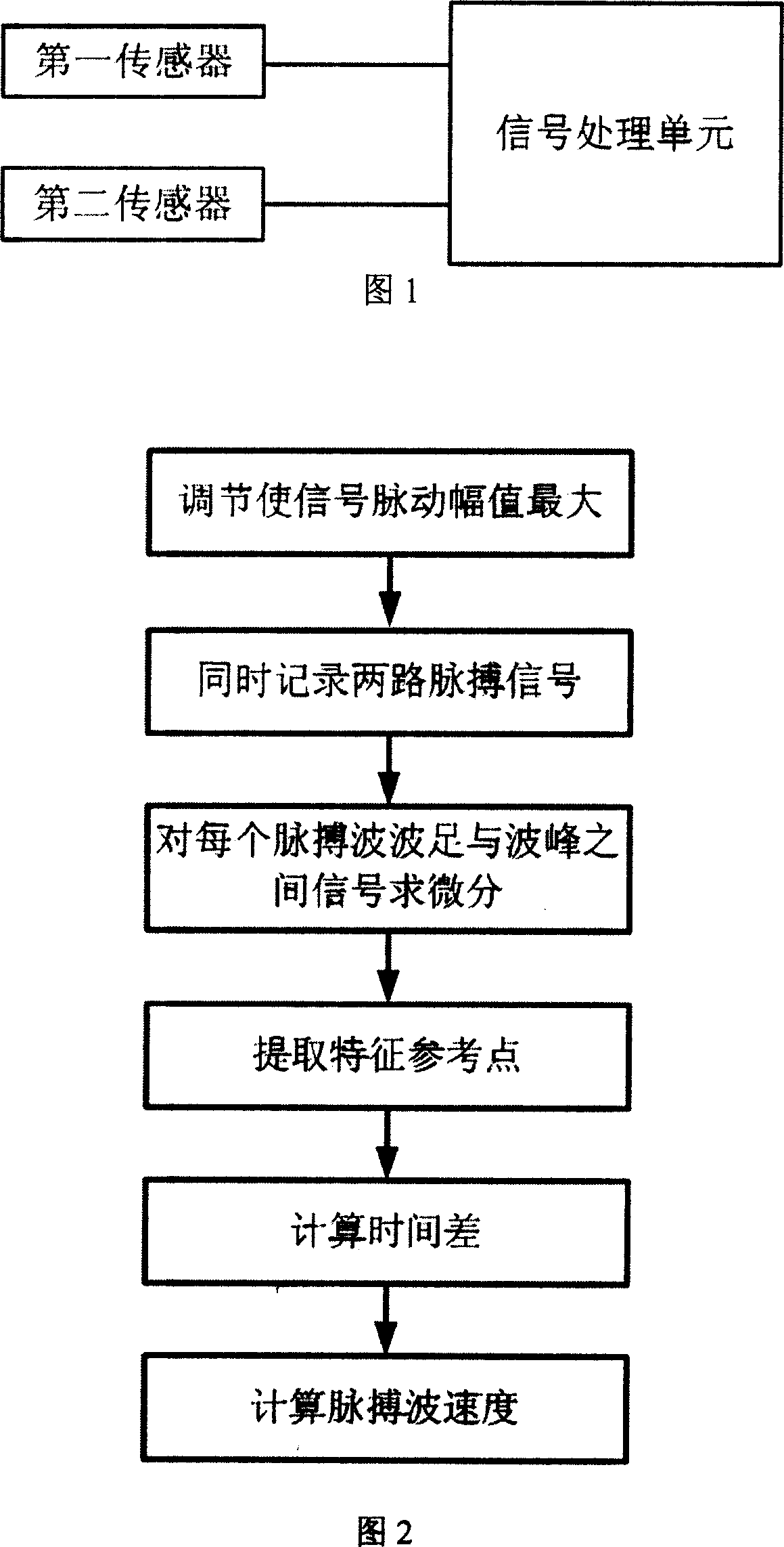
The invention discloses a device and method for measuring pulse wave velocity of human or mammal. The device comprises at least two sensors connecting with a signal processing element, wherein at least one of the first and second sensors is a diffused silicon pressure sensor. The signal processing element comprises amplifying circuits, a filter circuit, an analog to digital conversion circuit, and a main control circuit in sequential connection. The sensors are connected to the corresponding amplifying circuits respectively. The signal processing element also comprises signal separation circuit for separating transducer spikes. The method comprises obtaining maximum pulse signals, simultaneous recording two pulse wave signals with certain distance Delta s, abstracting characteristic reference point, calculating time interval difference Delta t of the signals, and calculating the pulse wave velocity. The device has the advantages of high safety, convenient operation, and good low-frequency response. The method has the advantages of reduced calculation amount, determined reference point, and high accuracy.

Description

technical field [0001] The invention relates to a method and a device for measuring pulse wave velocity, in particular to a device and a method for measuring the pulse wave velocity of a human body or a mammal. Background technique [0002] The cyclic contraction and relaxation of the heart causes the blood velocity, flow rate and vibration of the vessel wall in the arterial vessel to propagate along the arterial vessel. The propagation velocity of the pulse wave is directly related to the elasticity of the arterial tube. The greater the hardness of the blood vessel, the greater the pulse wave velocity. Therefore, the degree of elasticity of the arterial vessel can be evaluated by measuring the pulse wave velocity. [0003] Pulse wave velocity is defined as the ratio of the distance between two measurement points to the pulse wave propagation time. Known device and method for measuring pulse wave transit time, such as the technology disclosed in the Chinese Patent No. CN998...

Claims


Application Information

Patent Timeline
IPC IPC(8): A61B5/024A61B5/0285G06F19/00
Inventor 虞钢李婷蒋雄京王晓东李沈王立新宁伟健郑彩云
Owner INST OF MECHANICS - CHINESE ACAD OF SCI
Learn More