Multi-domain routing computation method and system
A computing method and computing system technology, applied in the field of communications, can solve the problem of inability to achieve end-to-end separation of routing calculations, and achieve the effects of easy separation of routing calculations, reduction of traffic, and elimination of rollback risks.
- Summary
- Abstract
- Description
- Claims
- Application Information
AI Technical Summary
Problems solved by technology
Method used
Image
Examples
Embodiment 2
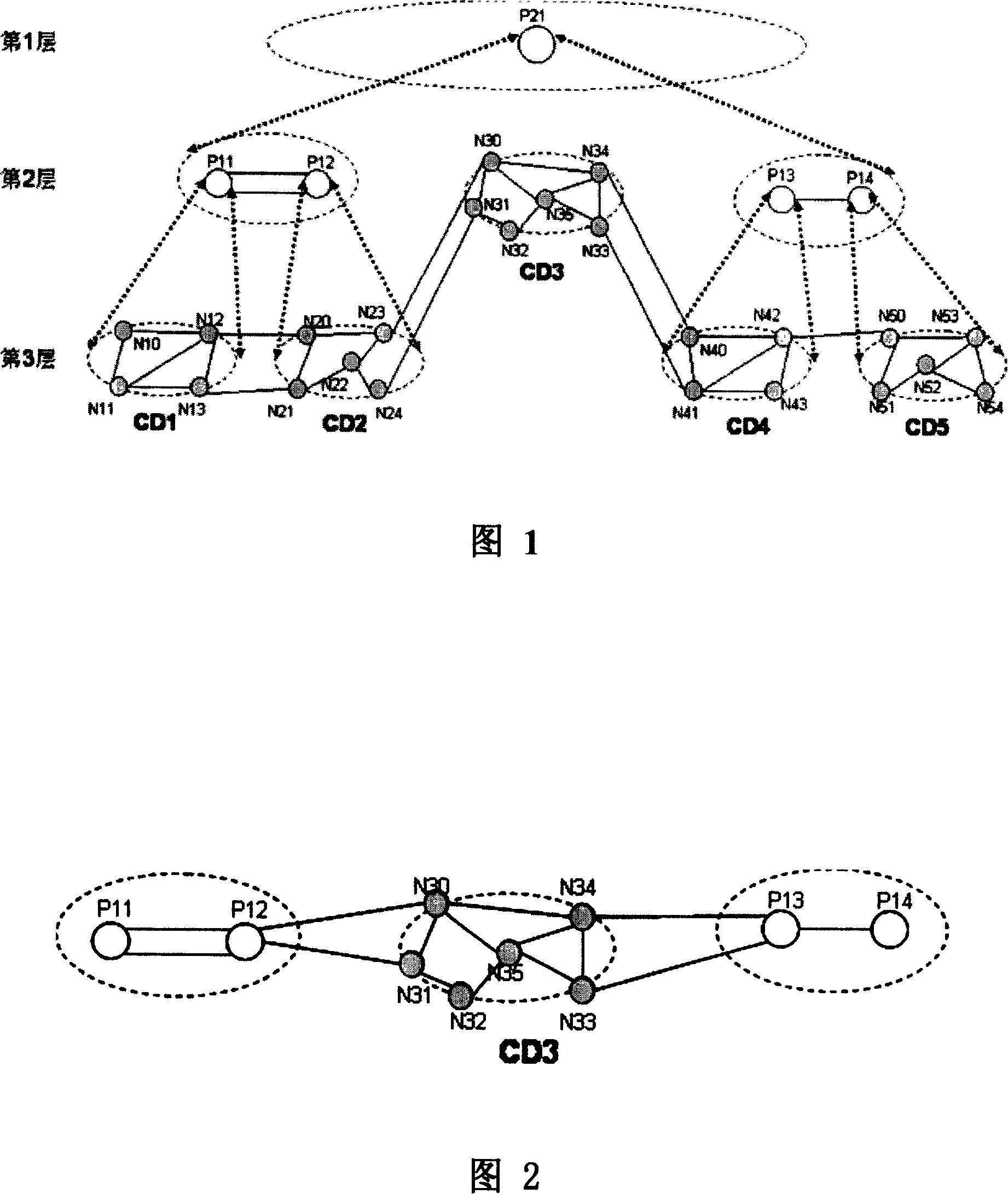
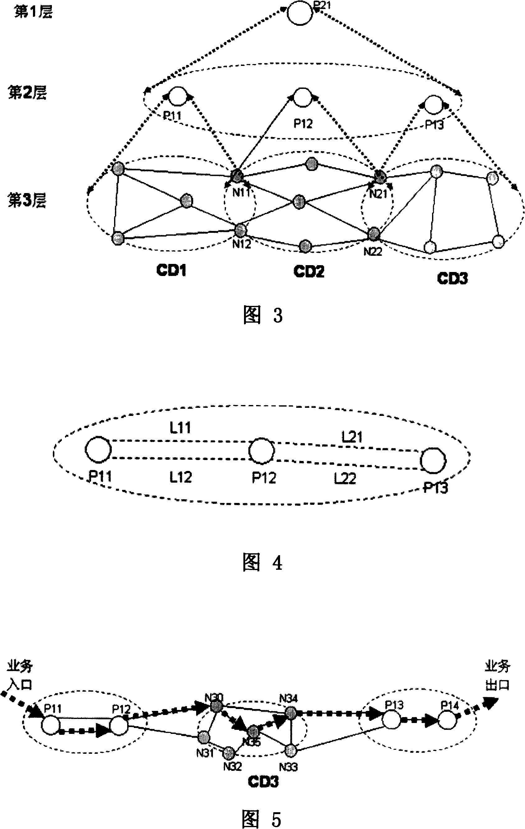
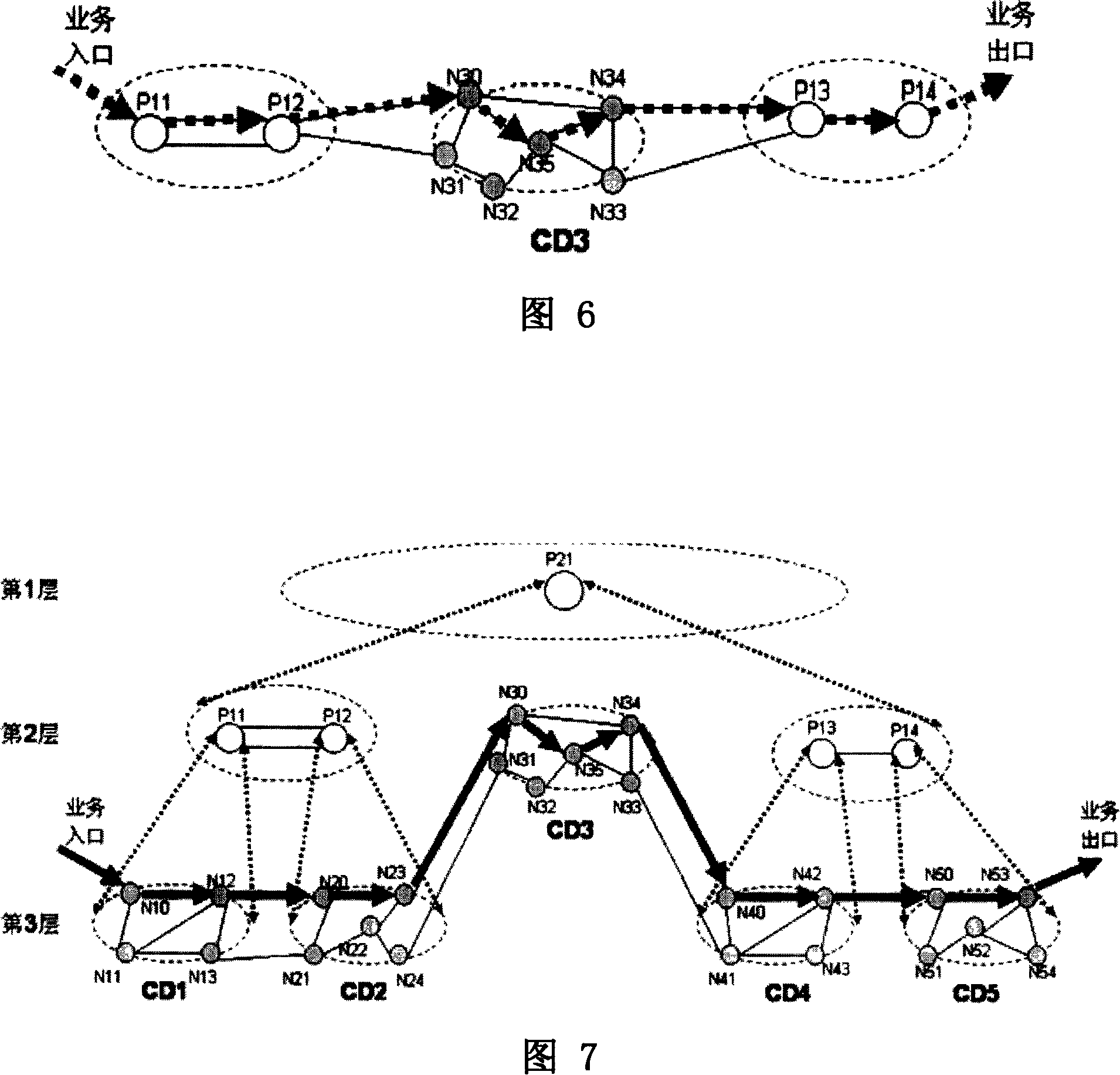
[0048] In the case of method embodiment 2, when the user initiates an order to establish a service from N10 to N53, the route calculation includes the following steps:
[0049] Step A: Determine the path computation unit whose computation domain can include both N10 and N53. This includes steps:
[0050] Step A1. The source node N10 requests the path computation unit P11 corresponding to its computation domain to perform route computation;
[0051] Step A2.P11 finds that N53 is not in its own computing domain, that is to say, the computing domain of P11 cannot contain both N10 and N53, so it will forward the routing calculation request to the direct upper layer path computing unit, that is, the path computing unit P21;
[0052] Step A3.P21 finds that N10 is in the calculation domain of its own directly lower-level path calculation unit P11, and finds that N53 is in the calculation domain of its own directly lower-level path calculation unit P14, that is to say, P21 finds that...
Embodiment 3
[0062] In the case of method embodiment 3, when the user initiates an order to establish a service from N10 to N53, the route calculation includes the following steps:
[0063] Step A: Determine the path computation unit whose computation domain can include both N10 and N53. This includes steps:
[0064] Step A1. The source node N10 requests the path calculation unit P11 corresponding to its calculation domain to perform route calculation; the source node notifies the sink node N53 to perform route calculation (here can also be notified by P11), and N53 requests the calculation domain that contains it. The corresponding path calculation unit P14 performs route calculation;
[0065] Step A2.P11 finds that N53 is not in its own computing domain, that is to say, the computing domain of P11 cannot contain both N10 and N53, so it will forward the routing calculation request to the direct upper layer path computing unit, that is, the path computing unit P21, and at the same time it...
Embodiment 4
[0076] In the case of method embodiment 4, when the user initiates an order from the network manager to establish a service from N10 to N53, the route calculation includes the following steps:
[0077] Step A: Determine the path computation unit whose computation domain can include both N10 and N53. At this time, the network management determines that P21 is a path computation unit whose computation domain can include both N10 and N53 through pre-saved information.
[0078] Step B: P21 and each path calculation unit in the lower layer of P21 jointly complete route calculation. This step is basically the same as step B in method embodiment 2, and will not be repeated here.
PUM
 Abstract
Description
Claims
Application Information
 - R&D
- Intellectual Property
- Life Sciences
- Materials
- Tech Scout
- Unparalleled Data Quality
- Higher Quality Content
- 60% Fewer Hallucinations
Browse by: Latest US Patents, China's latest patents, Technical Efficacy Thesaurus, Application Domain, Technology Topic, Popular Technical Reports.
© 2025 PatSnap. All rights reserved.Legal|Privacy policy|Modern Slavery Act Transparency Statement|Sitemap|About US| Contact US: help@patsnap.com


