Plasma display device

A plasma display and discharge unit technology, applied to solid cathode parts, cold cathode tubes, etc., can solve problems such as hindering the improvement of xenon gas efficiency and scattered wall charge distribution, and achieve the effect of improving jitter characteristics and improving discharge efficiency

Inactive Publication Date: 2007-12-05
LG ELECTRONICS(NANJING) PLASMA CO LTD
View PDF0 Cites 0 Cited by
  • Summary
  • Abstract
  • Description
  • Claims
  • Application Information

AI Technical Summary

Problems solved by technology

[0021] Especially, when increasing the content of xenon gas (Xe) in the discharge cell in order to improve the discharge efficiency of the plasma display, the wall charge distribution in the transparent electrode 11a caused by the address electrode 22 will become more scattered when the discharge cell is discharged. hampered by the increased efficiency of xenon

Method used


Image

  • Plasma display device
  • Plasma display device
  • Plasma display device

Examples


Embodiment Construction

[0045] In order to further illustrate the above-mentioned purpose, structural features and effects of the present invention, the PDP of the present invention will be described in detail below with reference to the accompanying drawings.

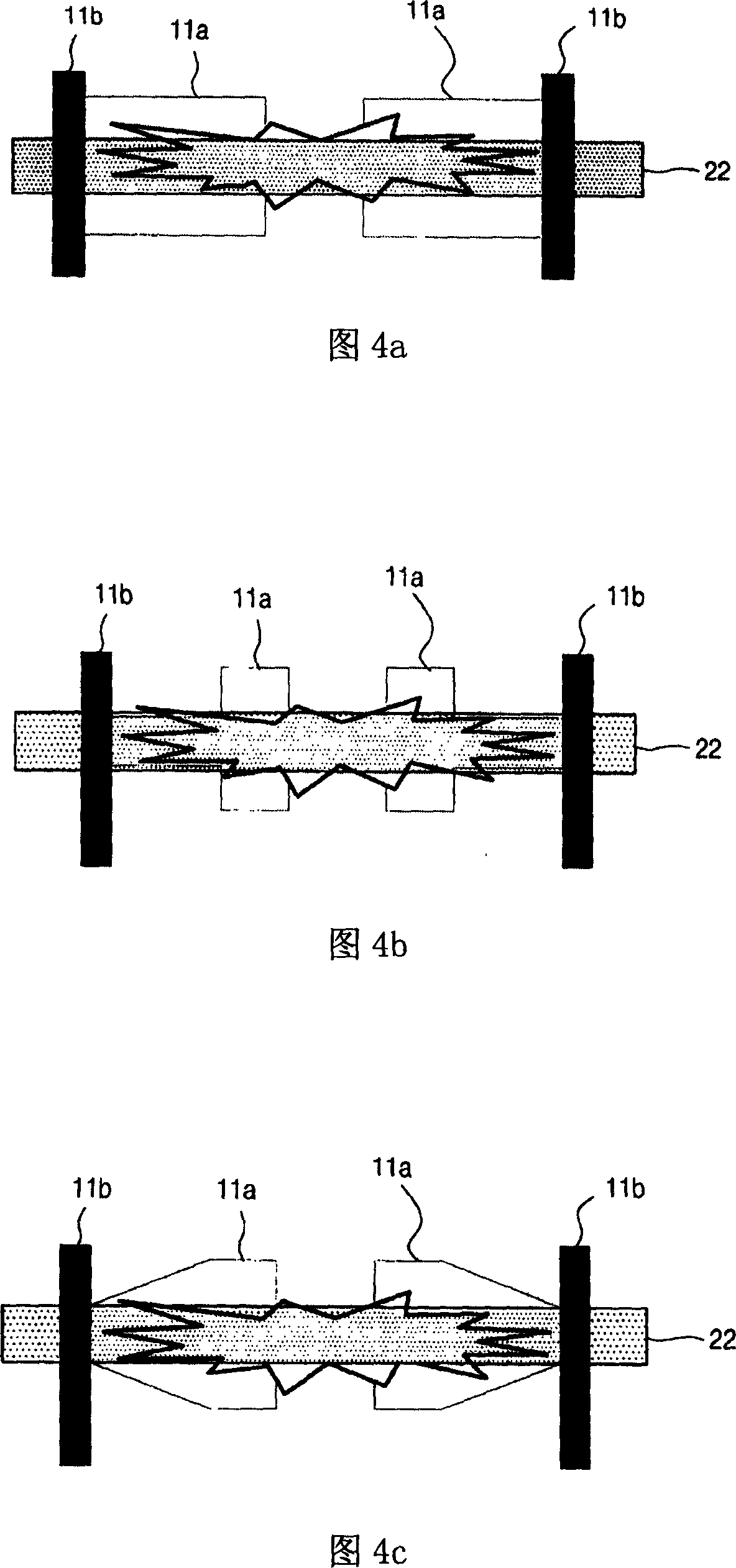
[0046] 7a to 7c are schematic diagrams of electrode structures in the discharge cells of the plasma display of the present invention.

[0047] First, in the electrode structure shown in 7a, the transparent electrode 11a is arranged on the front substrate in a quadrangular structure. The transparent electrodes 11a of such a quadrangular structure are arranged at both ends of the discharge cells where the bus electrodes 11b are located, between two transparent electrodes 11a, and the two transparent electrodes 11a face each other. In addition, the area of ​​the corresponding address electrode 22 inside the discharge cell is wider than the area of ​​the transparent electrode 11a, and the vertical width of the address electrode 22 in the discharg...


PUM


Abstract

The invention relates to a PDP (plasma display panel), especially a PDP able to raise discharging efficiency and improve dither characteristic as discharging by forming addressing electrodes matching with transparent electrode structure. And the PDP comprises: a front substrate equipped with scan electrodes and sustain electrodes; a rear substrate equipped with addressing electrodes staggered with the scan electrodes and the sustain electrodes; barriers for partitioning discharging cell regions on the rear substrate, where the scan electrodes and the sustain electrodes are respectively composed of transparent electrodes and bus electrodes, and in a discharging cell, the area of the addressing electrode is more than the maximum area of the transparent electrode.

Description

technical field [0001] The invention relates to a plasma display. In particular, it is a plasma display that can improve the discharge efficiency by improving the structure of the address electrodes. Background technique [0002] Generally, in a plasma display, a partition wall formed between a front substrate and a rear substrate made of soda-lime glass constitutes one discharge cell. Then, each unit is filled with a main discharge gas containing neon (Ne), helium (He) or a mixed gas of neon and helium (Ne+He) and a small amount of inert gas such as xenon (Xe). When a discharge is generated by a high-frequency voltage, vacuum ultraviolet rays (Vacuum Ultraviolet rays) are generated, so that the phosphors formed between the partition walls emit light, so that screen display can be performed. [0003] FIG. 1 is a schematic diagram showing a general structure of a plasma display device. As shown in FIG. 1, for a PDP, a front substrate 10 for displaying a picture and a rear ...

Claims


Application Information

Patent Timeline
Patent Type & Authority Applications(China)
IPC IPC(8): H01J17/49H01J17/04
Inventor 李炳俊
Owner LG ELECTRONICS(NANJING) PLASMA CO LTD
Why Eureka
Try Eureka