Screen, rear projector, projection system, and image display unit
A screen and image light technology, applied in the fields of rear projection projectors, screens, projection systems and image display devices, can solve problems such as image blurring, and achieve the effects of reducing flicker, suppressing noise, and reducing energy consumption.
- Summary
- Abstract
- Description
- Claims
- Application Information
AI Technical Summary
Problems solved by technology
Method used
Image


Examples
Embodiment approach 1
[0096] FIG. 1A is a perspective view showing a schematic configuration of the rear projection projector 120 of this embodiment, and FIG. 1B is a side sectional view of the rear projection projector 120 shown in FIG. 1A. The rear projection projector 120 of this embodiment modulates the light emitted from the light source with a light modulation element, and is a rear projection type projector that enlarges and projects the modulated light on the screen 20.
[0097] As shown in FIG. 1A, the rear projection projector 120 includes a screen 20 for projecting images; a box 90 installed on the back of the screen 20. A front end mask 88 is provided on the box 90 under the screen 20, and openings 38 for outputting sounds from speakers are provided on the left and right sides of the front end mask 88.
[0098] Hereinafter, the internal structure of the cabinet 90 of the rear projection projector 120 will be described.
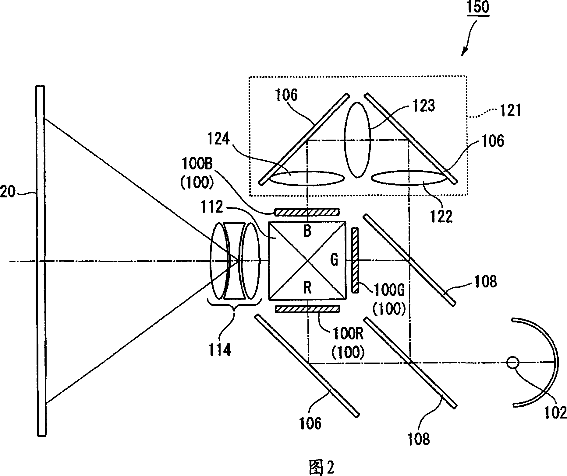
[0099] As shown in FIG. 1B, a projection optical system 150 is arrange...
Embodiment approach 2
[0127] Hereinafter, Embodiment 2 of the present invention will be described with reference to FIG. 6. 6 is a schematic configuration diagram of the screen main body in this embodiment, and FIGS. 7A and 7B are exploded views of the screen main body.
[0128] As shown in FIG. 6, the screen main body 40 is configured to add a flow in a direction orthogonal to the flow direction of the scatterer 34 flowing in the flow path 41. As shown in FIGS. 6 to 7B, a plurality of wall portions 42 (third partition walls) orthogonal to the partition walls 27 and wall portions 43 (third partition walls) orthogonal to the partition walls 28 are respectively provided. The wall portions 42, 43 extend perpendicularly from the front and back sides of the partition walls 27, 28 in the left-right direction (x direction), and have a length that never contacts the opposed partition walls 27, 28, that is, has a length longer than the adjacent partition walls 27, The interval between 28 is short in length. The...
Embodiment approach 3
[0133] Hereinafter, Embodiment 3 of the present invention will be described with reference to FIGS. 8 to 9B. Fig. 8 is a cross-sectional view in the focus direction (z direction) of the screen main body, and Figs. 9A and 9B are exploded views of the screen main body.
[0134] The screen main body 40 of the above embodiment is a screen main body in which the scatterer 34 flows in the left and right directions while reciprocating in the vertical direction of the screen main body 40. However, the screen main body 50 of this embodiment is configured as shown in FIG. 8 and is on the side of the scatterer 34. The opposing light-transmitting plates 23 reciprocate in the focusing direction (z direction), and flow toward the left-right direction (x direction) of the screen body 50 while reciprocating in the focusing direction (z direction).
[0135] As shown in FIG. 9A, the partition walls 51 and 52 of the present embodiment have the same length, and the length in the longitudinal directio...
PUM
 Abstract
Description
Claims
Application Information
 - R&D
- Intellectual Property
- Life Sciences
- Materials
- Tech Scout
- Unparalleled Data Quality
- Higher Quality Content
- 60% Fewer Hallucinations
Browse by: Latest US Patents, China's latest patents, Technical Efficacy Thesaurus, Application Domain, Technology Topic, Popular Technical Reports.
© 2025 PatSnap. All rights reserved.Legal|Privacy policy|Modern Slavery Act Transparency Statement|Sitemap|About US| Contact US: help@patsnap.com