
Light source module and lighting device for a vehicle

A technology for light source components and lamps, applied in the field of light source components and vehicle lamps, can solve problems such as the increase in the number of components, and achieve the effects of expanding the irradiation range and improving the luminous efficiency

Active Publication Date: 2007-11-28
KOITO MFG CO LTD
View PDF1 Cites 14 Cited by
  • Summary
  • Abstract
  • Description
  • Claims
  • Application Information

AI Technical Summary

Problems solved by technology

[0006] However, in the above-mentioned conventional light source module, since the fixing member for fixing the circuit board to the power feeding attachment is used, there is a problem of an increase in the number of parts due to the presence of the fixing member.

Method used


Image

  • Light source module and lighting device for a vehicle
  • Light source module and lighting device for a vehicle
  • Light source module and lighting device for a vehicle

Examples


Embodiment Construction

[0030] Hereinafter, the best mode for carrying out the light source unit and the vehicle lamp for carrying out the present invention will be described with reference to the accompanying drawings.

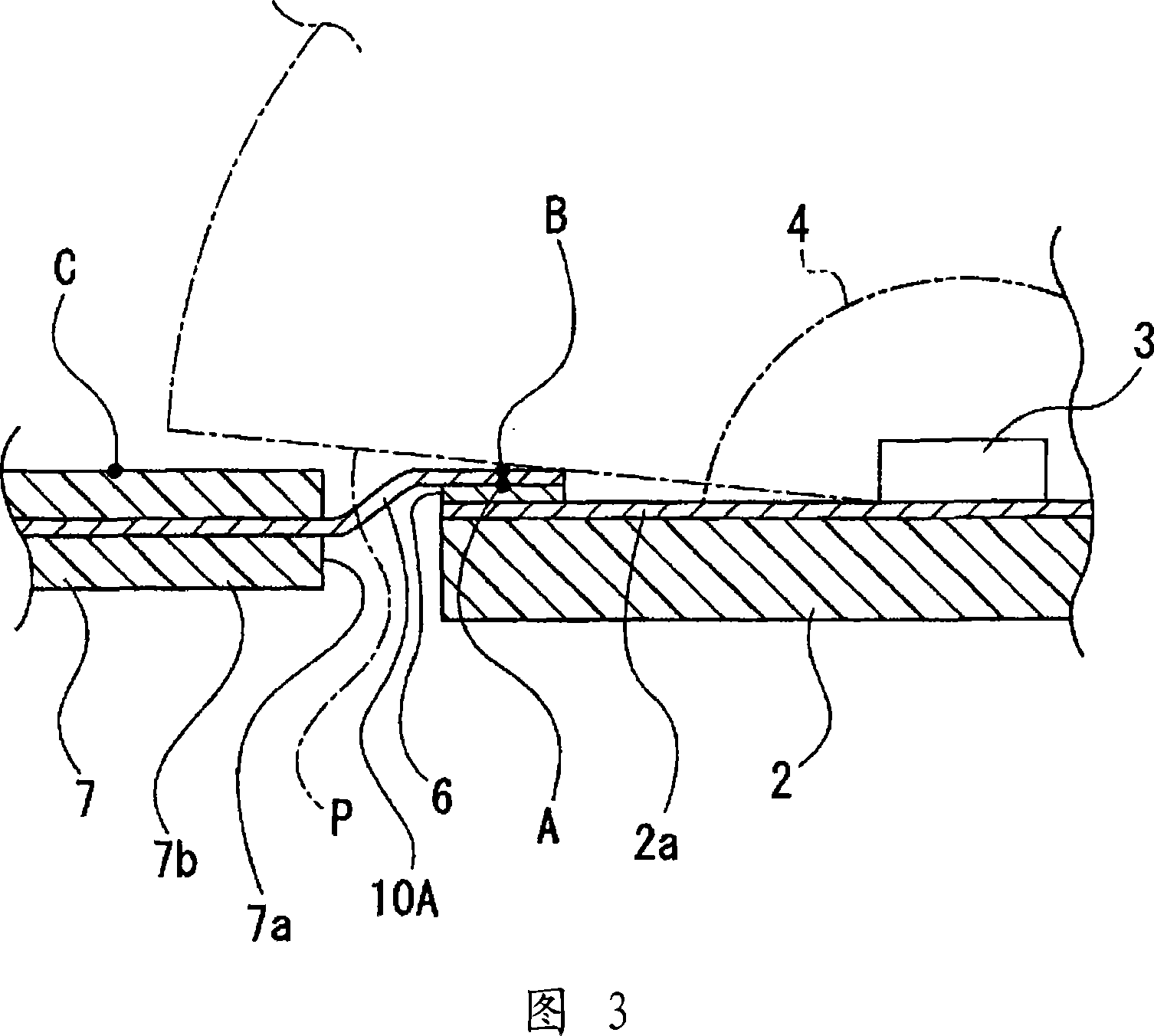
[0031] The light source unit 1 includes a ceramic circuit board 2, semiconductor light emitting elements 3 such as LED (light emitting diode) chips, a cover 4, and an attachment 5 for power supply (see FIG. 1 ).

[0032] For the ceramic circuit board 2 , for example, various substrates such as an aluminum nitride substrate, an alumina substrate, a mullite substrate, and a glass ceramic substrate can be used. On the ceramic circuit board 2, a pair of conductive patterns 2a, 2a extending from a central portion to side edges on opposite sides are formed.

[0033] Metal spacers 6 , 6 are bonded to end portions at respective outer positions of the conductive patterns 2 a , 2 a of the ceramic circuit board 2 . Since the metal spacers 6 and 6 are fixed to connection terminals of the power...


PUM


Abstract

Light source module and lighting device for a vehicle, to reduce the number of components in a light source module. The light source module is provided with a ceramic circuit board 2 on which conductive patterns 2a, 2a are formed, a semiconductor light-emitting element 3 which is arranged on the ceramic circuit board and connected to the conductive patterns, and a power feeding attachment 5 which is connected to the ceramic circuit board on which the semiconductor light-emitting element is arranged. The power feeding attachment is provided with power feeding parts 9, 9 connected to the external power supply, a plate-like part 7b which adjoins the position opposed to the outer periphery of the ceramic circuit board and is formed of a resin material, power feeding terminals 10, 10 which are formed in plate shape and protrude to the ceramic circuit board side from the plate-like part and of which tip part is superposed from the thickness direction and connected to a part of the conductive pattern. The power feeding terminals of the power feeding attachment and the conductive pattern of the ceramic circuit board are fixed and connected by welding.

Description

technical field [0001] The invention relates to a light source assembly and a vehicle lamp. Specifically, it relates to the technical field of reducing the number of parts by soldering and fixing the power feeding terminal of the power feeding accessory and the conductive pattern of the ceramic circuit board. Background technique [0002] There is a light source unit using a semiconductor light emitting element such as a light emitting diode (LED) as a light source (for example, refer to Patent Document 1). Vehicle lamps. [0003] In the light source module described in Patent Document 1, for example, a light emitting diode is mounted on a conductive pattern of a circuit board, and the circuit board is mounted on a power feeding attachment. The circuit board is fixed to the power feeding attachment by a fixing member (elastic member 503 in Patent Document 1), and the power feeding attachment with the circuit board fixed is attached to a heat radiator such as a bracket. ...

Claims


Application Information

Patent Timeline
Patent Type & Authority Applications(China)
IPC IPC(8): F21S8/10F21V23/00F21V19/00F21V29/00F21V5/04F21Y101/02H05B44/00
CPCF21S48/1159F21Y2101/02H01L2924/0002F21S48/1109F21Y2115/10F21S41/192F21S41/148H01L2924/00F21S41/147
Inventor 武田仁志时田主
Owner KOITO MFG CO LTD
Learn More