Apparatus for manufacturing moving hand-rail of passenger conveyer and method for manufacturing moving hand-rail
A manufacturing device and manufacturing method technology, applied to the manufacturing device and the manufacturing field of moving handrails of passenger conveyors, capable of solving problems such as hindering productivity and forming tooth shapes
- Summary
- Abstract
- Description
- Claims
- Application Information
AI Technical Summary
Problems solved by technology
Method used
Image
Examples
Embodiment 1
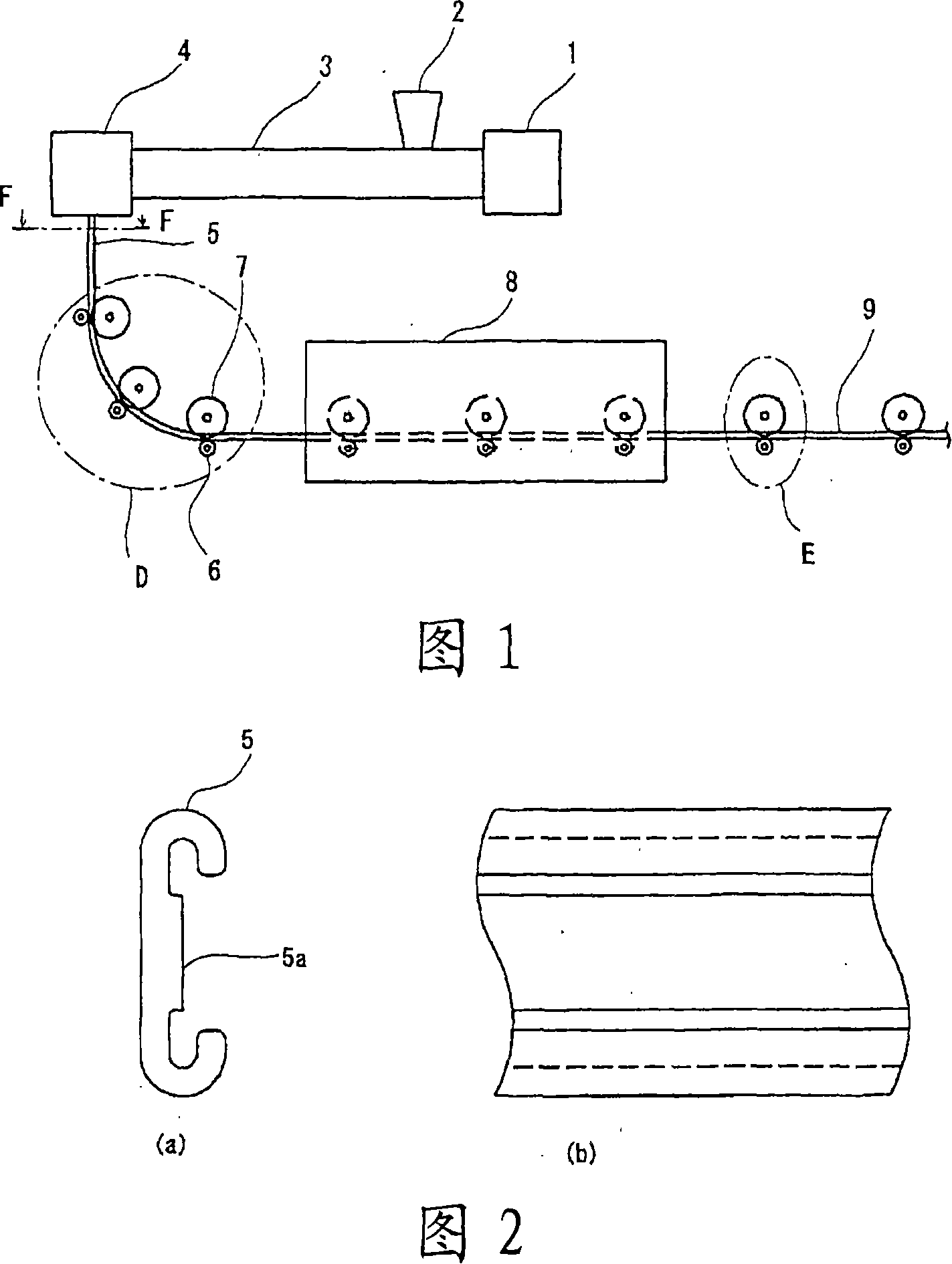
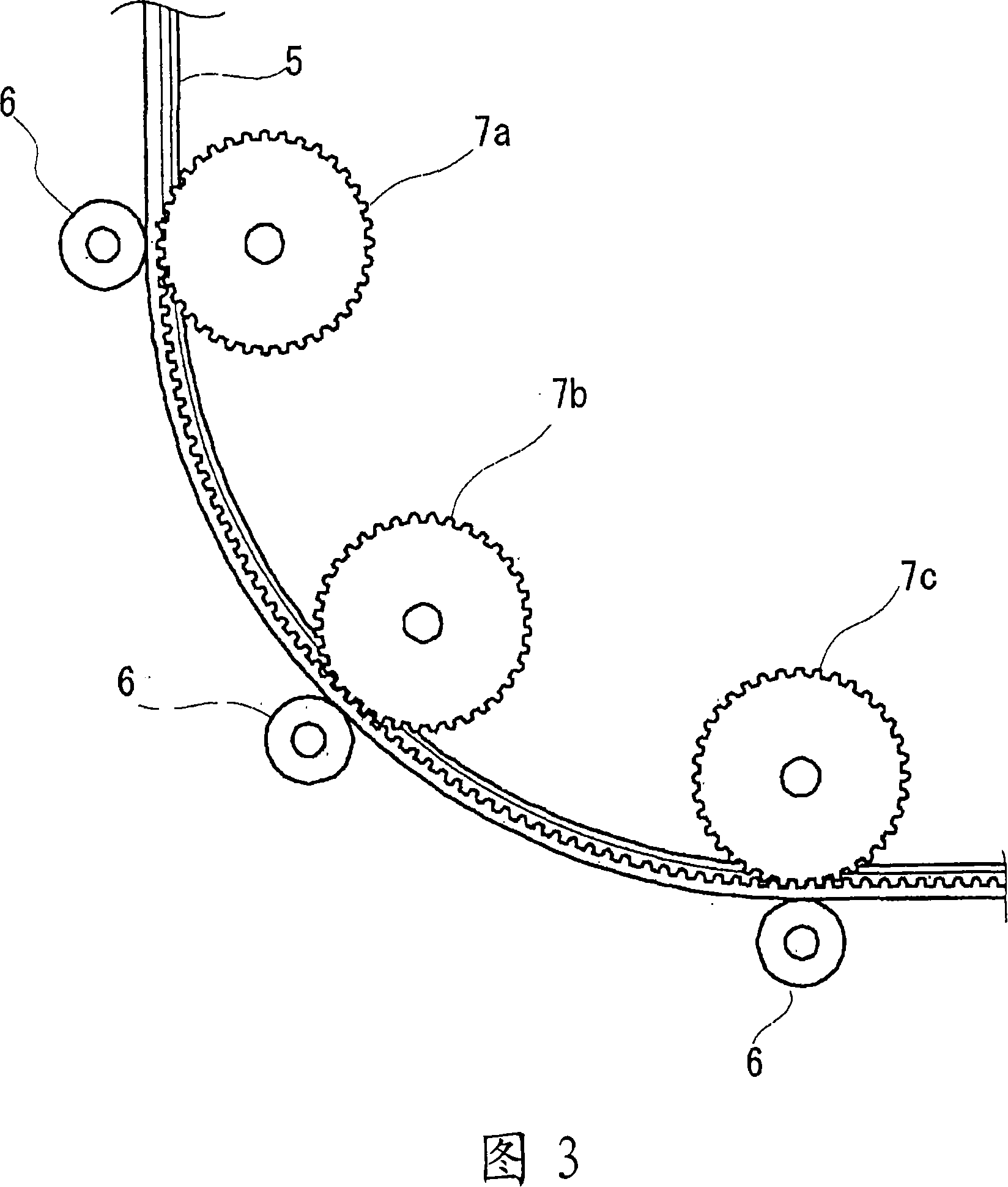
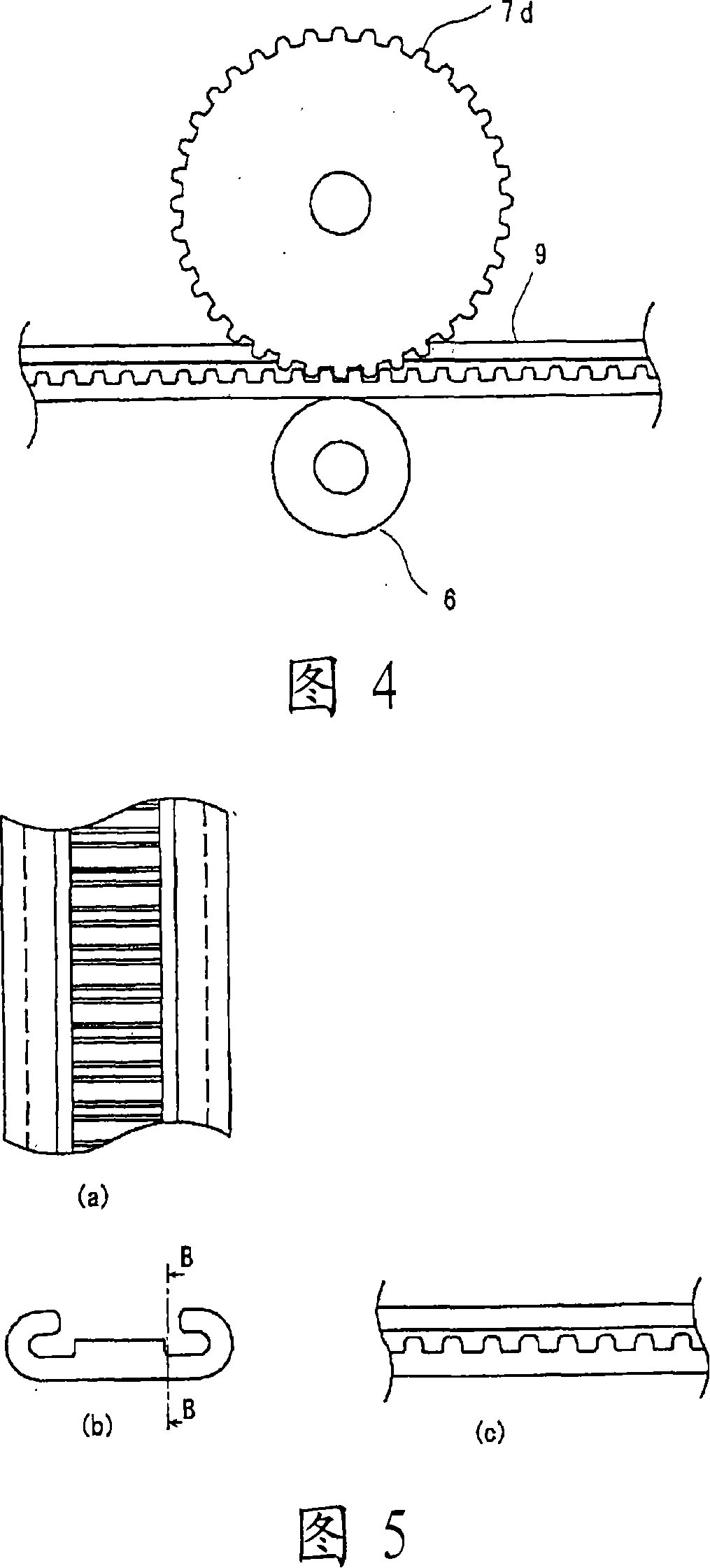
[0033] Fig. 1 is a diagram showing a manufacturing apparatus for a moving handrail of a passenger conveyor according to Embodiment 1 of the present invention.
[0034] In FIG. 1 , a raw material of thermoplastic resin, which is a main material of a moving handrail, is loaded from a material loading port 2 of a molding machine 1 .
[0035] The raw material loaded from the material loading port 2 is heated and mixed by the heater present in the molding machine 1, and then extruded from the extrusion port 4 by the extruder 3, and extruded as a material that has become approximately in the shape of a moving handrail. The moving handrail blank 5 of the above-mentioned thermoplastic resin.
[0036] Fig. 2 is a sectional view along line F-F of the handrail blank 5 of the passenger conveyor according to Embodiment 1 of the present invention. At the moment when the moving handrail blank 5 is extruded, the tooth profile has not yet been formed.
[0037] In the case where the moving ha...
Embodiment 2
[0050] Embodiment 2 describes the case of a manufacturing apparatus for manufacturing a handrail by joining previously formed rack-shaped blanks in a temperature range in which the handrail blanks are plastically deformable.
[0051] Fig. 6 is a diagram showing a manufacturing apparatus for the moving handrail 9 of the passenger conveyor according to the second embodiment of the present invention. In addition, parts not shown are the same as those in Embodiment 1, and the same reference numerals in FIG. 6 as those in FIG. 1 indicate the same or corresponding parts.
[0052] In Fig. 6, the raw material loaded from the material loading port 2 is heated and mixed by the heater present in the molding machine 1, and then extruded from the extrusion port 4 by the extruder 3, and the extruded product becomes The above-mentioned thermoplastic resin moving handrail blank 10 is substantially in the shape of a moving handrail.
[0053] Fig. 7 is a sectional view along line G-G of the mo...
Embodiment 3
[0062] Embodiment 3 describes the case of a manufacturing apparatus for manufacturing a handrail by bonding a preformed rack-shaped material and a handrail material.
[0063] Fig. 10 is a diagram showing an apparatus for manufacturing a moving handrail of a passenger conveyor according to Embodiment 3 of the present invention. In addition, the parts not shown are the same as those in Embodiment 2, and the same reference numerals in FIG. 10 as those in FIG. 6 indicate the same or corresponding parts.
[0064] In Fig. 10, the raw material loaded from the material loading port 2 is heated and mixed by the heater present in the molding machine 1, and then extruded from the extrusion port 4 by the extruder 3, and the extrusion becomes The above-mentioned thermoplastic resin moving handrail blank 10 is substantially in the shape of a moving handrail.
[0065] Fig. 11 is a structural view showing a rack-shaped blank 13 as a material at the time of manufacture of a manufacturing appa...
PUM
 Abstract
Description
Claims
Application Information
 - R&D
- Intellectual Property
- Life Sciences
- Materials
- Tech Scout
- Unparalleled Data Quality
- Higher Quality Content
- 60% Fewer Hallucinations
Browse by: Latest US Patents, China's latest patents, Technical Efficacy Thesaurus, Application Domain, Technology Topic, Popular Technical Reports.
© 2025 PatSnap. All rights reserved.Legal|Privacy policy|Modern Slavery Act Transparency Statement|Sitemap|About US| Contact US: help@patsnap.com


