Temporary storage

A technology of tensioning device and power device, which is applied to the device for accepting coins, transportation and packaging, instruments, etc., can solve problems such as poor operation and banknote jamming, and achieve the effect of simple and reasonable setting, precise control and large quantity

Active Publication Date: 2007-11-07
BEIJING C&W ELECTRONICS GRP
View PDF0 Cites 17 Cited by
  • Summary
  • Abstract
  • Description
  • Claims
  • Application Information

AI Technical Summary

Problems solved by technology

Due to the need to change the direction of the banknotes during the operation of the existing temporary storage device, the operation is not smooth, and the phenomenon of banknote jamming often occurs

Method used


Image

  • Temporary storage
  • Temporary storage
  • Temporary storage

Examples


Embodiment Construction

[0025] The following examples are used to illustrate the present invention, but are not intended to limit the scope of the present invention.

[0026] Definitions of several terms involved in the present invention:

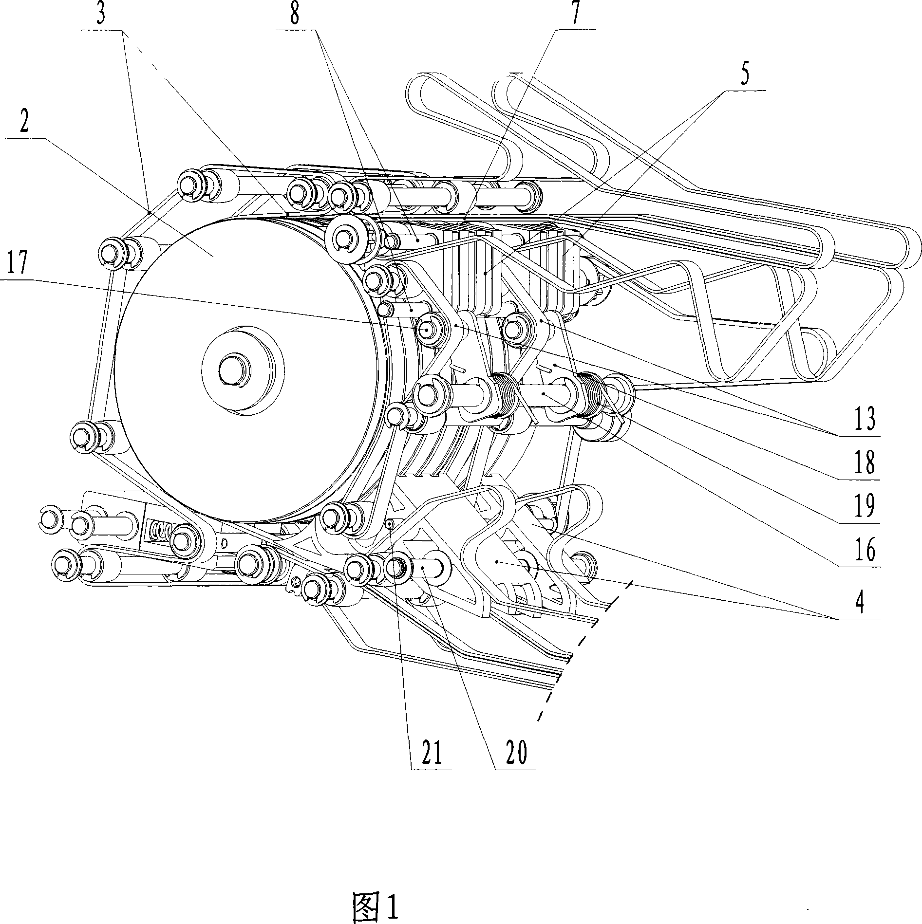
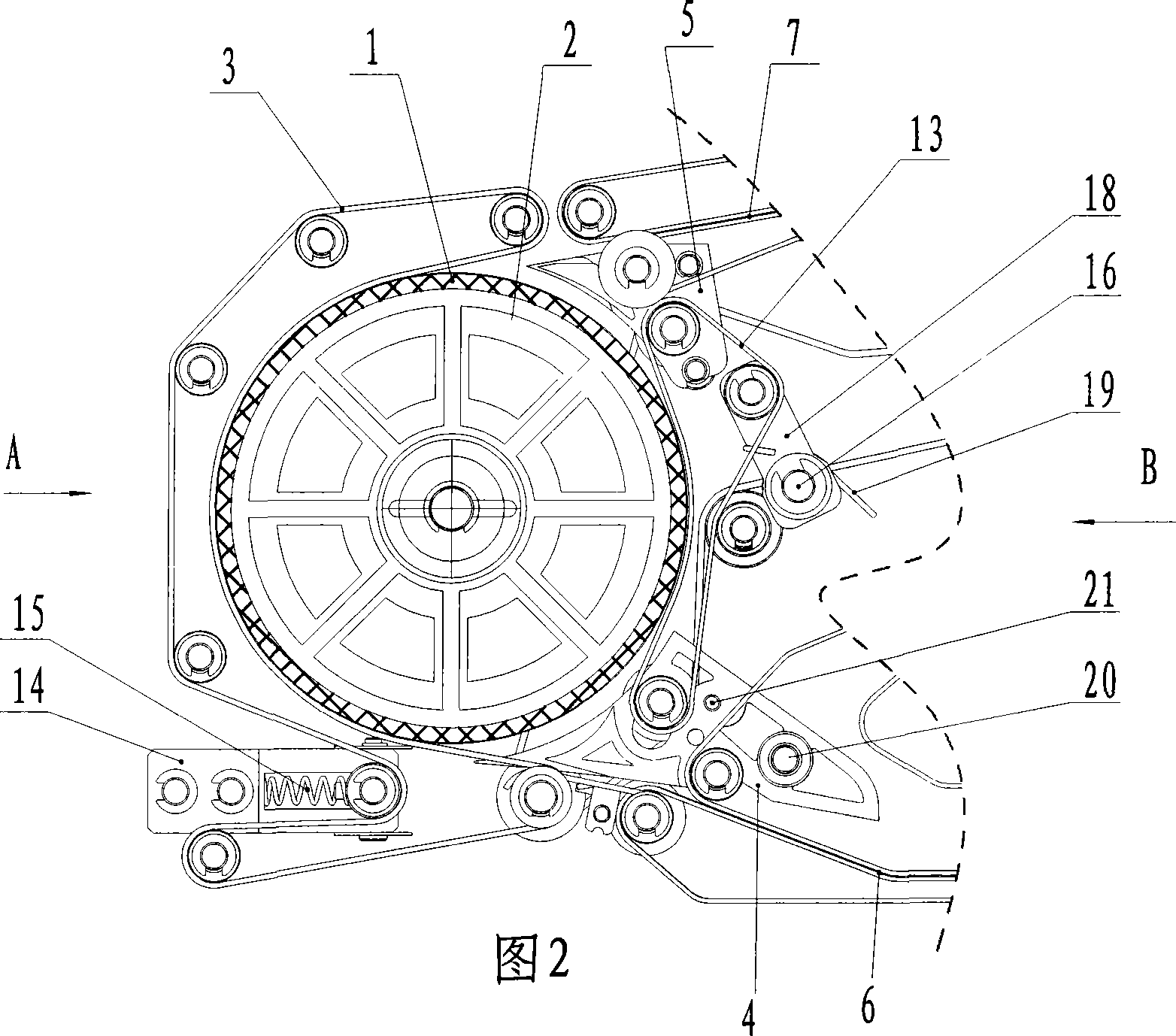
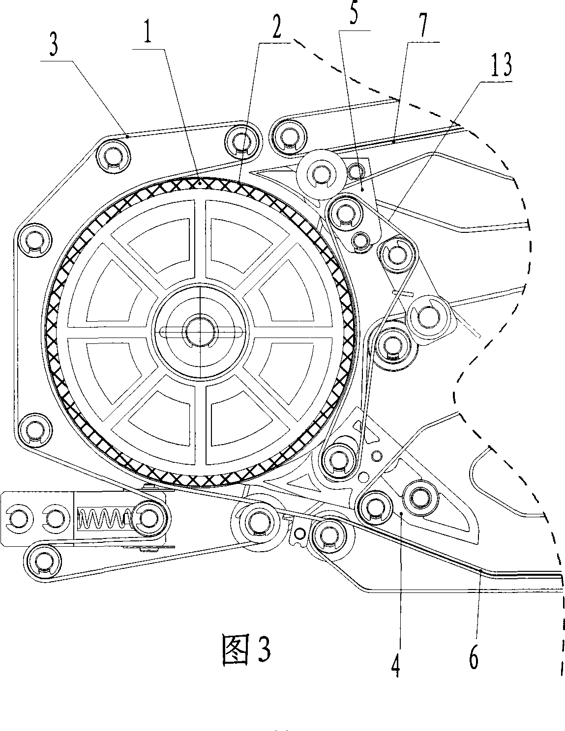
[0027] Temporary storage point at the belt II: when the banknote enters between the drum 2 and the temporary storage belt II 13, the front end of the banknote; this point can be any point determined by the matching part of the temporary storage belt II 13 drum 2, including the upper cut point and the lower cut point point, the preferred location is near the upper tangent point. The specific position of the temporary storage point at the belt II can be determined according to the control system.

[0028] Pause point after detection: the front end of the banknote when the banknote passes the last sensor (not shown in the figure) installed in the banknote-in channel 7 and waits for an instruction, this position is on the banknote-in channel 7 .

[0029] Banknote me...


PUM


Abstract

This invention relates to a temporary storing device used in bank paper processors including rollers between a money inlet channel and a money outlet channel, two sets of temporary storing belts wrapping the outer circle surfaces of the rollers driven by a power device and a fixed guide pad set between tops of the two belts for guiding in paper money and a flexible guiding block set between bottoms of the two belts for guiding out money.

Description

technical field [0001] The invention relates to a temporary storage device for a banknote processing machine. Background technique [0002] Banknote processing machines are now widely used in self-service equipment terminals such as automatic vending machines, automatic deposit machines, automatic deposit and withdrawal machines, and automatic exchange machines to process banknotes, and have broad market application prospects. The banknote processing machine can save manpower and material resources to the greatest extent, and can meet people's various transaction payment needs without time constraints. The existing banknote processing machine includes a conveying channel, a banknote input device, a detection device and a temporary storage device, wherein the temporary storage device is used for temporary storage of banknotes. The existing temporary storage device does not run smoothly because the banknotes need to change direction during operation, and banknote jamming ofte...

Claims


Application Information

Patent Timeline
Patent Type & Authority Applications(China)
IPC IPC(8): G07D11/00
CPCB65H29/51B65H2701/1912
Inventor 杨世伟白旭罗志强吴卫汪晓明潘必健
Owner BEIJING C&W ELECTRONICS GRP
Why Eureka
Try Eureka