Radiation beam source device

A technology of beam emission and emission source, applied in beam source, beam guide device, optics, etc., can solve problems such as low efficiency, and achieve the effect of high efficiency, efficient light distribution, and reduced energy loss

Inactive Publication Date: 2007-10-31
KONINK PHILIPS ELECTRONICS NV
View PDF2 Cites 0 Cited by
  • Summary
  • Abstract
  • Description
  • Claims
  • Application Information

AI Technical Summary

Problems solved by technology

[0004] The known method from US2002 / 0191236A1 has the disadvantage of low efficiency

Method used


Image

  • Radiation beam source device
  • Radiation beam source device
  • Radiation beam source device

Examples


Embodiment Construction

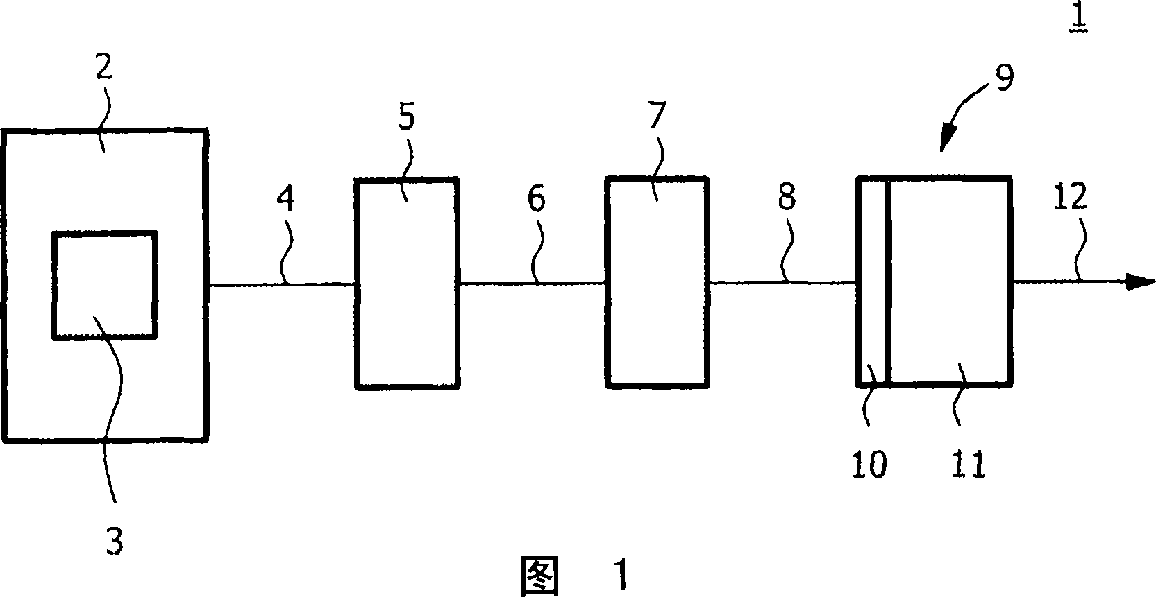
[0022] Fig. 1 shows a radiation source device 1 according to a first embodiment of the present invention. The emission source device 1 can be applied in optical storage systems, especially two-dimensional optical data storage and three-dimensional holographic storage. The optical storage system may use compact discs, digital versatile discs, blu-ray discs, storage media for holographic storage or other optical storage media. However, the emission source device 1 of the present invention is not limited to the data storage system mentioned here, but can also be used in other applications.

[0023] As shown in FIG. 1 , the radiation source device 1 includes a radiation-emitting element 2 . The beam emitting element 2 includes a semiconductor laser 3, and may include other elements such as lenses. The beam-emitting element 2 is emitting an elliptical emission beam 4 . The elliptical emission beam 4 may, for example, comprise an elliptical beam profile with an aspect ratio of 1:...


PUM


Abstract

For optical data storage applications, for example, for holographic storage applications, a radiation beam (12) with a flat intensity profile is needed. The radiation source device (1) of the invention comprises a beam shaper element (5) and a collimating element (7) between a semiconductor laser (3) and an output coupler (9) and provides such a radiation beam (12) with an increased efficiency. An external resonator is thereby provided. Further, a relatively fast tuning of the wavelength of the output radiation beam (12) can be provided.

Description

technical field [0001] The invention relates to a radiation source device for an optical storage system and to an optical data storage device comprising such a radiation source device. More specifically, the present invention relates to an emission source device and an optical data storage device for two-dimensional optical data storage, such as compact discs, digital versatile discs and Blu-ray disc memory and the like, and the three-dimensional optical memory is an application such as holographic memory and the like. Background technique [0002] Prior art document US6654183B2 describes a system for converting a light beam into a collimated flat-top beam. The system is capable of converting a substantially inhomogeneous input beam, such as a Gaussian beam, into a substantially uniform output beam. [0003] Prior art document US2002 / 0191236A1 describes a method for improving holographic recording using beam apodization. In this known method, the highly inhomogeneous inte...

Claims


Application Information

Patent Timeline
Patent Type & Authority Applications(China)
IPC IPC(8): G11B7/135G02B27/09G11B7/0065H01S5/14G11B7/125
CPCG11B7/1376H01S2302/00G11B7/1381H01S5/0656G02B19/0028G11B7/1362G11B7/0065G02B27/0916H01S5/141G02B19/0052H01S5/005G11B7/1398
Inventor G·特胡夫特J·J·H·B·施莱彭F·J·P·舒尔曼斯T·W·图克
Owner KONINK PHILIPS ELECTRONICS NV
Why Eureka
Try Eureka