
Drive unit for X-ray system

A drive unit and X-ray technology, applied in the field of X-ray devices, can solve the problems of no detectable feedback, insufficient positioning of X-ray tubes, etc., and achieve good feedback, precise and direct movement control, and direct control effects

Active Publication Date: 2007-10-31
KONINKLIJKE PHILIPS ELECTRONICS NV
View PDF2 Cites 3 Cited by
  • Summary
  • Abstract
  • Description
  • Claims
  • Application Information

AI Technical Summary

Problems solved by technology

Users operating known x-ray systems are often uncomfortable with remotely controlling the movement of the x-ray tube in this manner, since movement control is indirect, without any sensed feedback
Also, the remote control of the movement is sometimes not precise enough for the X-ray tube positioning, which is required by the respective inspection procedure

Method used


Image

  • Drive unit for X-ray system
  • Drive unit for X-ray system
  • Drive unit for X-ray system

Examples


Embodiment Construction

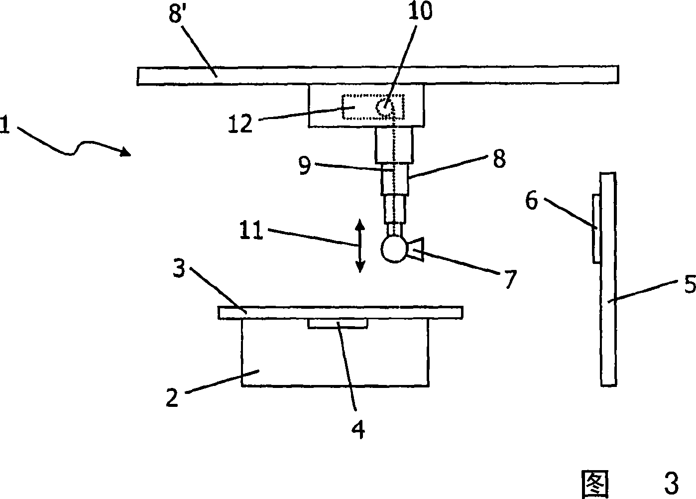
[0019] Referring to Fig. 3, an X-ray device 1 according to the invention is depicted. The X-ray apparatus 1 comprises a table 2 with a table top 3 for supporting a patient during an examination. The table 2 has a container 4 for X-ray film. Furthermore, a ledge 5 is provided, which also includes a container 6 for X-ray film. Such a ledge 5 can be used for examination of the patient in a standing position. An overhead x-ray source 7 directs the beam through the patient to the x-ray film below or behind the patient. The X-ray source 7 is mounted on a tube hanger 8 to support the X-ray source 7 and to enable the X-ray source 7 to move vertically and horizontally. The tube hanger 8 of the described x-ray device 1 can be extended or retracted via a telescopic section. These telescoping sections are telescopically movable by wires 9 which are guided by pipe hangers 8 and wound around pulleys 10 . The x-ray source can be raised or lowered (as indicated by arrow 11 ) by means of ...


PUM


Abstract

The invention relates to a drive unit (12) for vertical or horizontal movement of a component (7) of a diagnostic X-ray device (1), comprising a motor and gear unit (14), a pulley (10) mounted on a drive shaft (13) of the motor and gear unit (14), and traction means (9), e.g. a rope or a drive belt, wound around the pulley (10), the component (7) to be moved being either attached to the traction means (9) or connected with the drive unit (12). In order to provide a drive unit (12) enabling collision detection, emergency stop functionality, and improved handling with regard to control of the motion of the component (7) by an operator of the X-ray device (1), the invention proposes that the motor and gear unit (14) is rotatable about the axis of the drive shaft (13) against the elastic force of a balancing spring (15), wherein provision is made for a rotation sensor (17,24), which rotation sensor (17,24) is adapted for detecting a rotation of the motor and gear unit (14) and for generating a corresponding rotation detection signal.

Description

technical field [0001] The present invention relates to a drive unit for vertical or horizontal movement of components of X-ray diagnostic equipment, this drive unit includes a motor and a transmission unit, a pulley installed on the drive shaft of the motor and the transmission unit, and a pulley wound around the pulley Around the traction device, the device to be moved is attached to the traction device or connected with the drive unit. [0002] The invention also relates to an X-ray device comprising an X-ray source, an X-ray image detector facing the X-ray source, and at least one drive unit for the X-ray source or the X-ray image detector Move vertically and / or horizontally. Background technique [0003] In the field of medical diagnostic imaging, especially in the fields of fluoroscopy and radiography, a large range of equipment is currently commercially available. In conventional X-ray systems, as known for example from EP 0 068 929 A2 or US 4 435 830, during the ex...

Claims


Application Information

Patent Timeline
IPC IPC(8): A61B6/00
CPCA61B6/4476F16M11/046F16M11/24A61B6/447F16M11/18F16M13/027F16M2200/044F16P7/02A61B6/548A61B6/4464
Inventor H·芬克H·-H·施韦克U·迈耶-道奎J·克西科斯G·默德格耶西
Owner KONINKLIJKE PHILIPS ELECTRONICS NV
Learn More