
Method, test tool and test system for testing sensitivity of terminal receiver

A test tool and test system technology, applied in the field of communication, to achieve the effect of efficient BER test, accurate test data and high test efficiency

Active Publication Date: 2007-10-31
HUAWEI TECH CO LTD
View PDF0 Cites 22 Cited by
  • Summary
  • Abstract
  • Description
  • Claims
  • Application Information

AI Technical Summary

Problems solved by technology

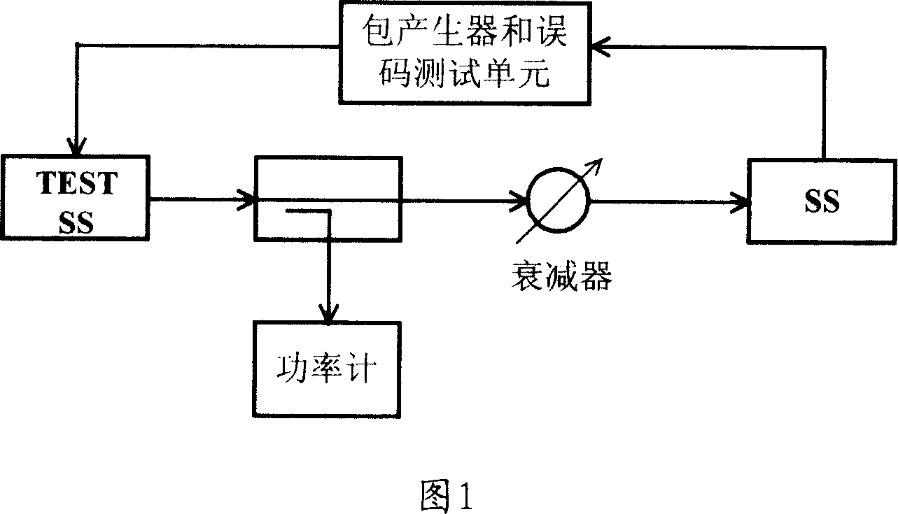
[0011] The purpose of the present invention is to provide a kind of method, test tool and test system that terminal receiver sensitivity is tested, when applying the present invention to test the receiver sensitivity of terminal, do not depend on TEST BS equipment, thus solve the problem of the prior art The receiver sensitivity of the terminal must be subject to the key issues of TEST BS equipment when performing BER tests

Method used


Image

  • Method, test tool and test system for testing sensitivity of terminal receiver
  • Method, test tool and test system for testing sensitivity of terminal receiver
  • Method, test tool and test system for testing sensitivity of terminal receiver

Examples


no. 1 example

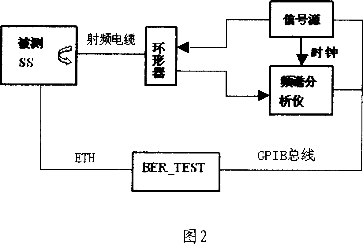
[0057] The first embodiment provided by the present invention is to utilize the air interface loopback mode to realize the test system of the receiver sensitivity of test SS by GPIB bus control signal source and spectrum analyzer, the structure of this test system is as shown in Figure 2, comprises as follows Components:

[0058]Signal source, SS under test, spectrum analyzer, test tool (BER_TEST) and circulator. The test tool is connected with the signal source and the spectrum analyzer through the GPIB bus, and connected with the SS under test through the Ethernet interface ETH. The air interface of the SS under test is connected to a signal source and a spectrum analyzer through a circulator, the signal source generates a wireless signal, and carries known data through the wireless signal (the data can be generated by the signal source or provided by other equipment to the signal source), and provide a synchronous clock to the spectrum analyzer through the wireless signal;...

no. 2 example

[0083] The second embodiment provided by the present invention is a test tool, which includes:

[0084] Parameter configuration unit, control unit, test unit and storage unit;

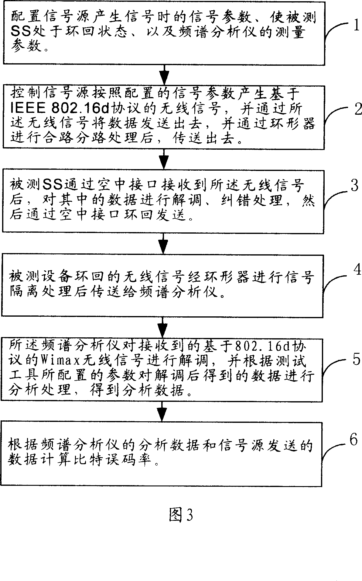
[0085] The parameter configuration unit configures the device under test to be in the loopback state, configures the parameters of the signal generated by the signal source, and configures the parameters of the spectrum analyzer. details as follows:

[0086] 1. The control unit of the test tool configures various parameters of the signal generated by the signal source through the GPIB bus, such as frequency point, power, frame length, bandwidth, CP, modulation mode, etc.

[0087] 2. Configure the SS under test to be in the loopback state by issuing commands from the maintenance network port, that is, the SS receiver first demodulates, corrects errors, and modulates the wireless signal sent by the signal source, and then sends it out from the air interface with appropriate power.

[0088] 3. Configure...


PUM


Abstract

The invention relates to testing method, testing tool and testing system of terminal receiver sensitivity, the core is: the testing tool controls the signal source to generate wireless signal and transmits known data to the equipment which is to be tested, the equipment demodulates and FEC decodes the data, then it is transmitted to the spectrum analyzer; the spectrum analyzer demodulates and decodes the wireless signal, and provides data to testing tool; the testing tool calculates error code based on the data of signal source and the received data. The invention does not depend on TEST BS equipment, and the invention can make test data accurate, the efficiency is high, besides the invention can be used in development, testing, manufacture and operating attestation testing of SS, it provides a scheme of testing sensitivity of SS receiver for device supplier and operator.

Description

technical field [0001] The invention relates to the communication field, in particular to a test technology for terminal receiver sensitivity. Background technique [0002] WiMax (Worldwide Interoperability for Microwave Access, Worldwide Interoperability for Microwave Access) is a broadband wireless access standard with broad market prospects, and it is mainly used in wireless metropolitan area networks. Based on the IEEE 802.16d protocol, it adopts OFDM (Orthogonal Frequency-division Multiplexing) multi-carrier transmission technology in the microwave and millimeter wave bands to provide high-speed data service air interface transmission. [0003] Receiver sensitivity is the most basic and important index to measure the performance of SS (Subscriber Station, WiMax terminal) receiver. Receiver sensitivity test is also called BER (Bit Error Rate, Bit Error Rate) test. Due to the new WiMax technology, suppliers only provide IEEE 802.16d protocol options for signal sources an...

Claims


Application Information

Patent Timeline
IPC IPC(8): H04B17/00H04B17/29
Inventor 王慧
Owner HUAWEI TECH CO LTD
Learn More