Track structure of magnetic floating traffic and manufacturing method therefor

A manufacturing method and track technology, which is applied to tracks, roads, buildings, etc., can solve problems such as the complexity of track beam manufacturing, and achieve the effects of convenient adjustment of line alignment, simple method, and reduced manufacturing complexity and difficulty

Active Publication Date: 2007-10-31
TONGJI UNIV
View PDF4 Cites 18 Cited by
  • Summary
  • Abstract
  • Description
  • Claims
  • Application Information

AI Technical Summary

Problems solved by technology

This technical solution also has the problem of complicating the manufacture of the track beams

Method used


Image

  • Track structure of magnetic floating traffic and manufacturing method therefor
  • Track structure of magnetic floating traffic and manufacturing method therefor
  • Track structure of magnetic floating traffic and manufacturing method therefor

Examples


Embodiment Construction

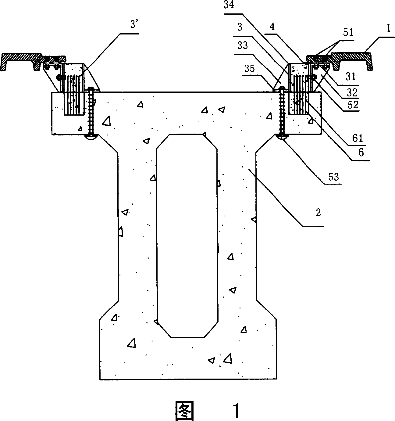
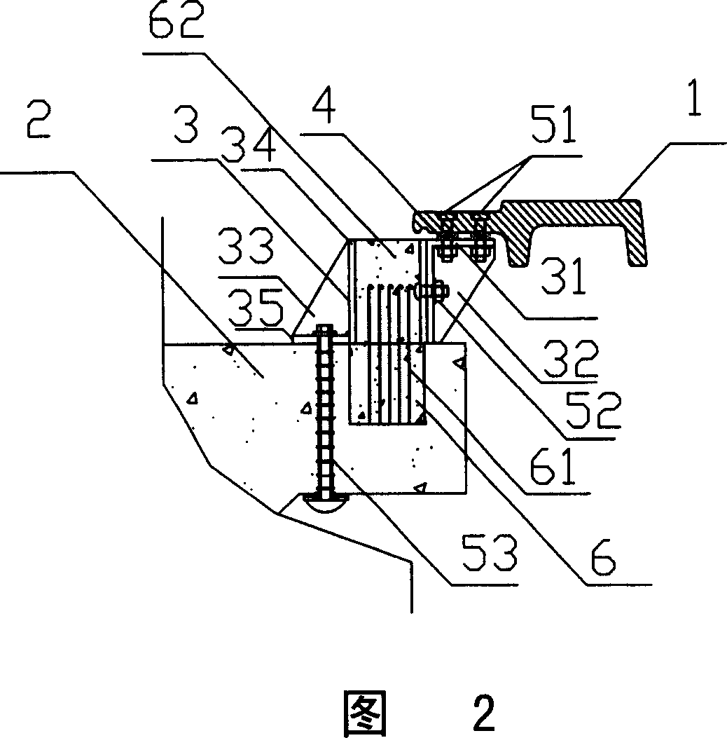
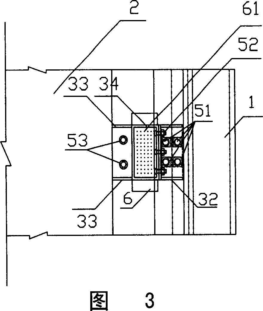
[0032] Please refer to Figs. 1-8, all the same components are represented by the same symbols among the figures. It can be seen from the figures that the track structure of the present invention mainly includes: track beam 2, guide rails 1 located on both sides of the upper surface of track beam 2, and a connecting structure connecting these two parts. The connection structure mainly includes pads 3 and fasteners such as bolts, and gaskets 4 can also be provided according to adjustment requirements. The difference between the present invention and the prior art is that pads 3 are arranged between the track beam 2 and the guide rail 1 . The so-called "block 3" here is different from the padding member for adjustment used in the past, but a structural connecting piece that connects the guide rail 1 and the track beam 2 .

[0033] 1 to 4 show a track structure according to a first embodiment of the present invention. In this embodiment, the block 3 is a prefabricated steel comp...


PUM


Abstract

The invention provides a track structure of magnetic floating traffic, comprising a track beam, a track at two sides of the upper face of the track beam, and a connecting structure connecting aforementioned two parts, wherein the connecting structure comprises a fixer and a block between the track beam and the track as one structure connector. The invention also provides a relative production. The invention has uniform track beam type, saved template, reduced production complexity, easy track adjustment via arranging the curvature track all on the block, with simple method and low cost. And the invention uses industry tool to form a track distributor to position the track, thereby adjusting the track linearity easily and improving working efficiency.

Description

technical field [0001] The present invention generally relates to a track structure, in particular to a track structure for low-speed maglev traffic and a manufacturing method thereof. Background technique [0002] In the maglev system driven by a constant-wire linear asynchronous motor, the two sides of the track beam are suspended inverted "U"-shaped steel ferromagnetic guide rails. The electromagnet for suspension and guidance fixed on the maglev train is just placed under the guide rail, and the iron core is in a "U" shape, opposite to the inverted "U" guide rail. When the train is running, the electromagnet generates a suction force to attract the guide rail from below, and the train uses this suction force to levitate. When the car body electromagnet and the guide rail are laterally misaligned, oblique attraction will be generated between them, and the horizontal component force of the attraction will correct the misalignment, thereby realizing the guiding function. ...

Claims


Application Information

Patent Timeline
Patent Type & Authority Applications(China)
IPC IPC(8): E01B25/30
Inventor 曾国锋曹雪峰朱志伟李三珍袁亦竑
Owner TONGJI UNIV
Why Eureka
Try Eureka