Status detection device
一种状态检测、设备的技术,应用在测量装置、测量流量/质量流量、液体/流体固体测量等方向,能够解决没有提出解决方法等问题
- Summary
- Abstract
- Description
- Claims
- Application Information
AI Technical Summary
Problems solved by technology
Method used
Image
Examples
no. 1 example
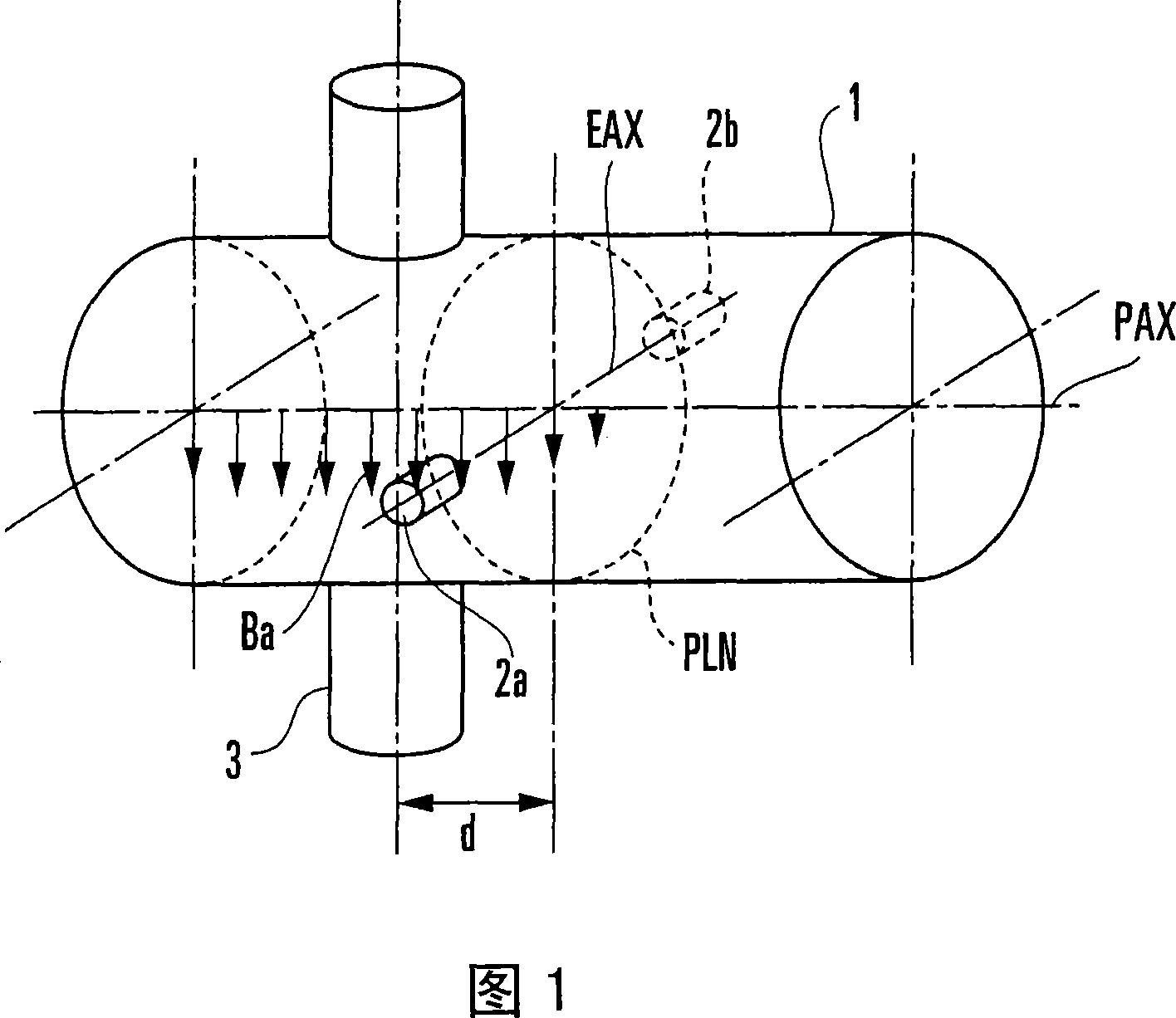
[0373] Next, a first embodiment of the present invention will be described in detail. This embodiment uses the first principle described above. The state detection device according to this embodiment includes an exciting coil and a pair of electrodes, and has the same configuration as the state detection device shown in FIG. 1 except for a signal processing system. This embodiment uses the first extraction method as a method of extracting the _A / _t component from the resultant vector, and obtains the first parameter independent of the excitation frequency. Examples of first parameters are the liquid level or the deposition state of substances adhering to the inside of the measuring pipe.
[0374] When an exciting current having an angular frequency ω0 is supplied to the exciting coil 3 and the first parameter is p1, the inter-electrode electromotive force E110 is expressed by the following equation from equations (19), (65) and (75).
[0375] E110=rk[p1]·ω0·b1·exp{j·(π / 2+θ1+...
no. 2 example
[0421] Next, a second embodiment of the present invention will be described. This embodiment is the same as the first embodiment except that an exciting coil is added to the state detection device, and this embodiment uses the second principle described above. That is, the state detection device of this embodiment includes two exciting coils and a pair of electrodes, and has the same configuration as the state detection device shown in FIG. 5 except for the signal processing system. Therefore, the principle of this embodiment will be described using reference numerals in FIG. 5 . If the second field coil to be added is placed on the same side as the first field coil, the resulting configuration is a redundant configuration of the first embodiment. Therefore, it is necessary to place the second exciting coil on a different side from the first exciting coil with respect to the plane including the electrodes. This embodiment uses the first extraction method as a method of extra...
no. 3 example
[0483] Next, a third embodiment of the present invention will be described. The state detection device according to this embodiment includes two exciting coils and a pair of electrodes, and has the same configuration as the state detection device shown in FIG. 5 except for a signal processing system. Therefore, the principle of this embodiment will be described using reference numerals in FIG. 5 . This embodiment uses the second extraction method as a method of extracting the _A / _t component from the resultant vector to obtain the first parameter independent of the excitation frequency.
[0484]Assume that a first exciting current having an angular frequency ω0 is supplied to the first exciting coil 3a, a second exciting current having an angular frequency ω0 and having a phase difference of Δθ2+π with respect to the first exciting current is supplied to the second exciting coil 3b, and The first parameter is p3. In this case, from the equations (30), (68) and (75), the elec...
PUM
 Abstract
Description
Claims
Application Information
 - R&D
- Intellectual Property
- Life Sciences
- Materials
- Tech Scout
- Unparalleled Data Quality
- Higher Quality Content
- 60% Fewer Hallucinations
Browse by: Latest US Patents, China's latest patents, Technical Efficacy Thesaurus, Application Domain, Technology Topic, Popular Technical Reports.
© 2025 PatSnap. All rights reserved.Legal|Privacy policy|Modern Slavery Act Transparency Statement|Sitemap|About US| Contact US: help@patsnap.com


