Linear actuator

A linear drive, linear drive technology, applied in the direction of fluid pressure actuation device, servo motor, servo meter circuit, etc., to achieve the effect of kinematics design optimization

Inactive Publication Date: 2011-07-06
FESTO AG & CO KG
View PDF1 Cites 1 Cited by
  • Summary
  • Abstract
  • Description
  • Claims
  • Application Information

AI Technical Summary

Problems solved by technology

Here, an adjustable throttle inserted into the exhaust gas flow substantially limits the exhaust gas flow rate in order to limit the stroke speed of the drive unit
However, if the linear drive is to be operated with different strokes, in other words, a stroke movement ending with end position damping starts at a different starting position, this also leads primarily to disadvantages.

Method used


Image

  • Linear actuator
  • Linear actuator

Examples


Embodiment Construction

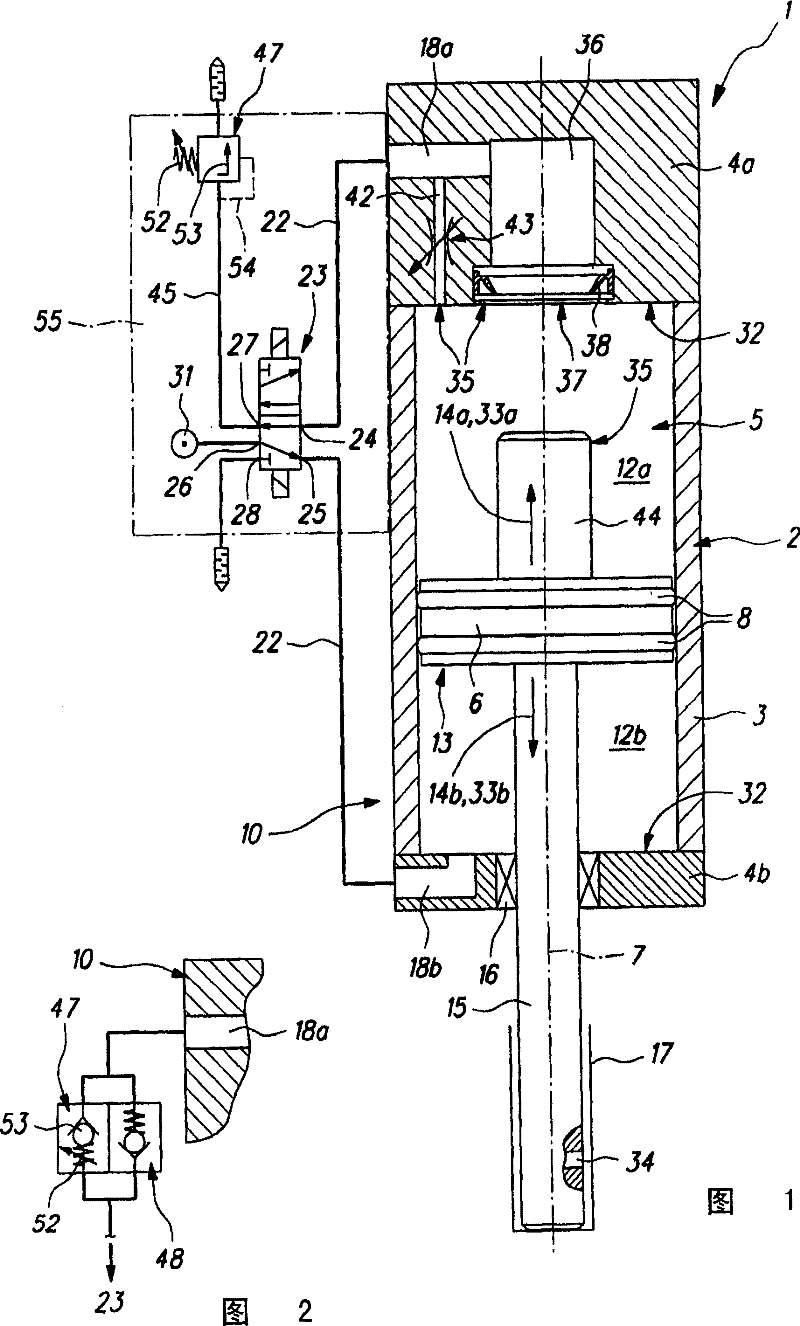
[0023] The linear drive generally designated 1 includes a pneumatic, ie compressed-air driven linear drive 10 , which is oriented vertically in the exemplary embodiment. However, the linear drive 10 can also be operated in other orientations.

[0024] The linear drive 10 comprises an elongated housing, referred to as the drive housing 2 , which consists, for example, of a housing tube 3 and two housing covers 4a, 4b arranged on its end faces. .

[0025] An elongated interior 5 is defined by the driver housing 2 , in which a driver piston 6 is accommodated displaceably in the longitudinal direction 7 of the driver housing 2 .

[0026] In the region of its outer circumference, the driver piston 6 has annular sealing means 8 which come into sealing contact with the peripheral walls of the inner space 5 so that the inner space 5 is divided into sealed portions by the driver piston 6 . Two axially successive working chambers 12a, 12b.

[0027] The drive piston 6 is part of a dri...


PUM


Abstract

The present invention presents a linear driving apparatus (1), which includes a linear driver (10) with a damping mechanism (35) which is integrated and permits terminal location damping. The air-exhaustion of at least one work space (12a) in the linear driver (10) is controlled by the pressure-limiting valve mechanism (47). When the work space (12a) at the flow-out side is provided with the predetermined lowest pressure, the pressure-limiting mechanism can be allowed to exhaust the air. With this mode, it can guarantee the damping action of the terminal location which is far and away independent to the application situation.

Description

technical field [0001] The invention relates to a linear drive having a pneumatic linear drive with a drive unit separating two working chambers from one another in the drive housing, the drive unit being loaded with controlled compressed air Linearly displaceable from at least one starting position into at least one end-of-travel position, the linear drive is equipped with damping mechanisms which, during the damping phase before reaching at least one end-of-travel position, make the work from the current outflow side The outflow rate of the air discharged from the chamber ( ) is lowered in order to brake the drive unit. Background technique [0002] A linear drive of this type known from DE 20 2005 018 038 U1 comprises a pneumatic linear drive which is equipped with a damping mechanism for braking the speed of its drive unit. These damping mechanisms act in a short damping phase, which can take place before one or two end-of-travel positions of the drive unit are reache...

Claims


Application Information

Patent Timeline
Patent Type & Authority Patents(China)
IPC IPC(8): F15B15/14B29C49/00
CPCF15B2211/30525F15B11/044F15B2211/7053F15B2211/75F15B2211/5153F15B2211/473F15B2211/41527F15B15/222F15B2211/50518F15B2211/40515F15B2211/555F15B2211/327
Inventor G·戈默尔R·斯特劳布
Owner FESTO AG & CO KG
Why Eureka
Try Eureka