
Adjustable stepless electricity loss emergency braking device used for pressure machine

A braking device and emergency braking technology, applied in the direction of presses, manufacturing tools, etc., can solve the problems of complex structure and high cost, and achieve the effects of short response time, improved work stability, and reduced work noise.

Inactive Publication Date: 2007-10-24
金志良
View PDF1 Cites 5 Cited by
  • Summary
  • Abstract
  • Description
  • Claims
  • Application Information

AI Technical Summary

Problems solved by technology

Its structure is complex and the cost is high

Method used


Image

  • Adjustable stepless electricity loss emergency braking device used for pressure machine
  • Adjustable stepless electricity loss emergency braking device used for pressure machine
  • Adjustable stepless electricity loss emergency braking device used for pressure machine

Examples


Embodiment Construction

[0023] In order to make the technical means, creative features, goals and effects achieved by the present invention easy to understand, the present invention will be further described below in conjunction with specific illustrations.

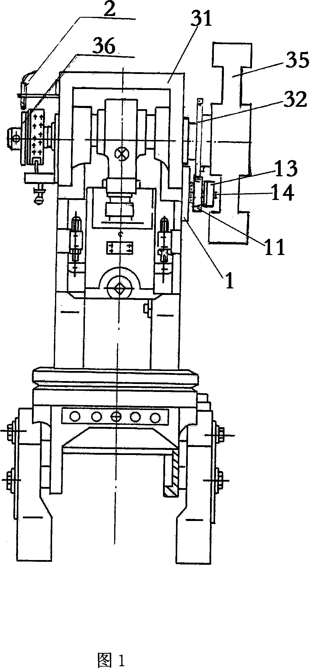
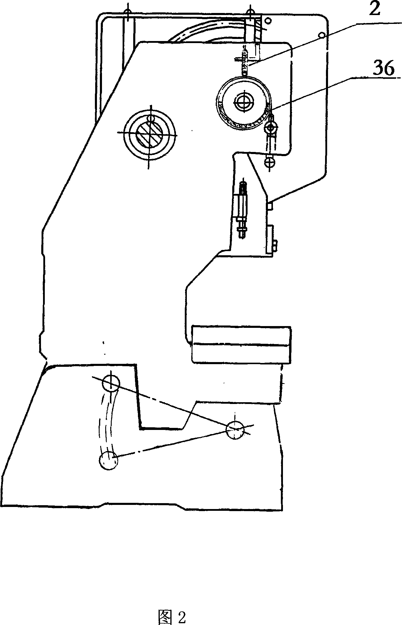
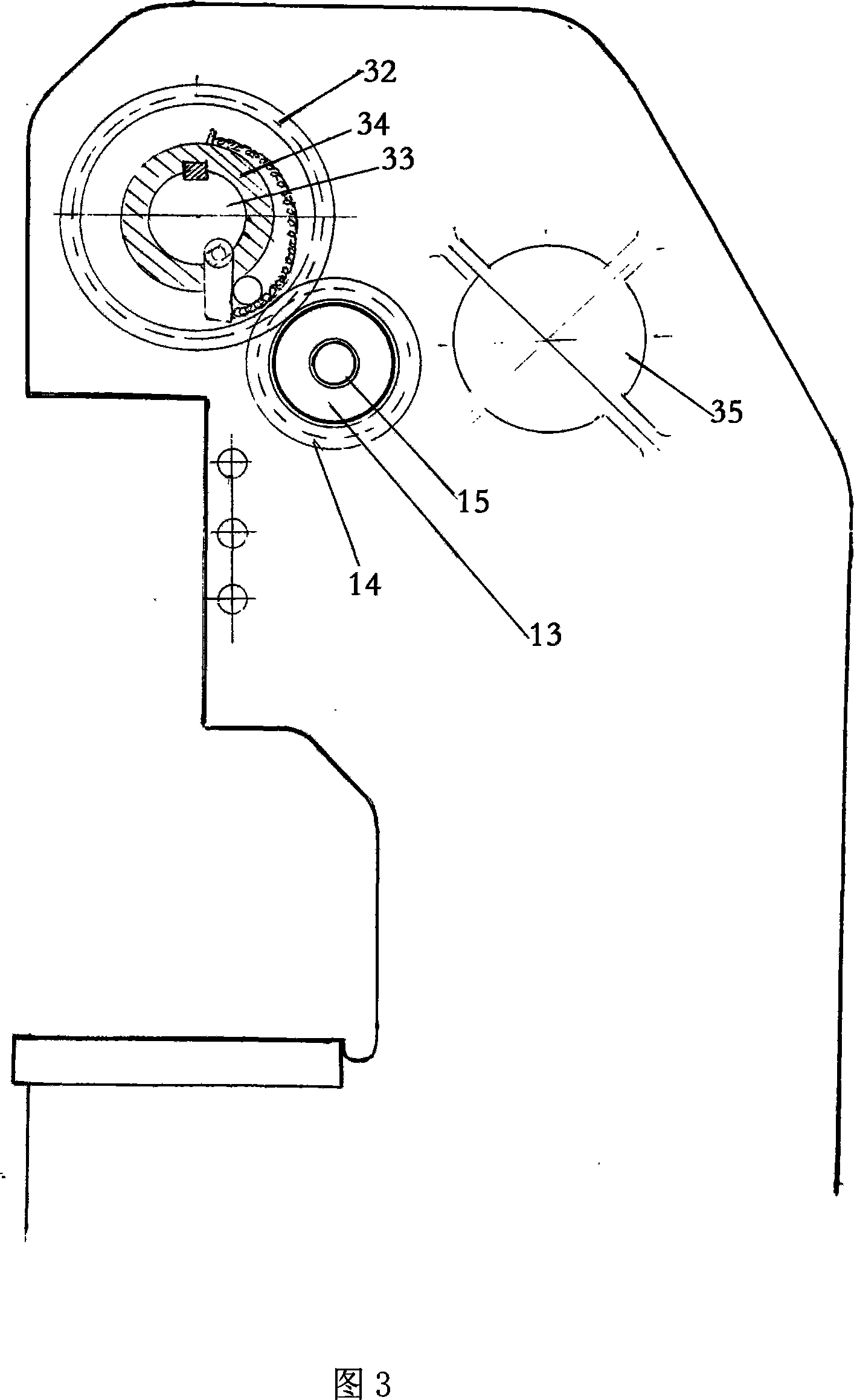
[0024] As shown in Fig. 1, Fig. 2 and Fig. 3, an adjustable stepless power-off emergency braking device for a press includes a power-off brake 1, and its installation base 11 is installed on a press wall plate 31, and the installation base 11 A central shaft 12 is provided on it, and the central shaft 12 is the installation basis for the components of the entire power-off brake 1. An electromagnetic clutch 13 is arranged on it, and the armature 131 of the electromagnetic clutch 13 faces the side of the installation base 11. The armature 131 and the A transmission gear 14 is arranged between the mounting bases 11, which meshes with the large gear 32 of the press, and the flywheel 35 is coaxially arranged with the large gear 32.

[0025] Referring...


PUM


Abstract

The invention provides an adjustable limitless sudden brake device for press machine. It features in an electric free brake device that comprises an installation base of the central shaft on the press machine wall, electromagnetic clutch towards the installation base, drive gear between the installation base and the armature, and the approach switch controlling the electromagnetic clutch installed on the top of the crankshaft of the press machine. It realizes one time adjustable feature, with short response time, stability, less noise.

Description

technical field [0001] The invention generally relates to a brake device, in particular to an adjustable stepless power-off emergency brake device for a press. Background technique [0002] At present, most of the rigid clutch presses used in industrial production in my country do not have emergency braking control devices. During the operation, many work-related accidents are brought to the press operator. A large number of severed fingers and hand accidents occur from time to time. It causes great mental and physical pain to the operator. At the same time, it also brings many troubles and economic losses to business owners, and brings many unstable and disharmonious factors to the society. [0003] The power-off brake (safety brake) is a special brake that belongs to the product range of single-plate electromagnetic clutches. This product started in the late 1970s. Although it was developed late, it developed rapidly. It is a major development of the single-plate elect...

Claims


Application Information

Patent Timeline
Patent Type & Authority Applications(China)
IPC IPC(8): B30B15/10
Inventor 金粤海
Owner 金志良
Learn More