Anisotropy ferrite magnet and motor
A ferrite magnet and anisotropic technology, applied in the field of ferrite magnets, can solve the problems of increasing the requirement of characteristics, and achieve the effect of excellent characteristics and reducing torque fluctuation
Active Publication Date: 2007-10-17
TDK CORPARATION
View PDF1 Cites 7 Cited by
- Summary
- Abstract
- Description
- Claims
- Application Information
AI Technical Summary
Problems solved by technology
[0006] According to Patent Document 1, it is possible to provide an anisotropic ferrite magnet capable o
Method used
View moreImage
Smart ImageViewing Examples
Examples
 PUM
 Abstract
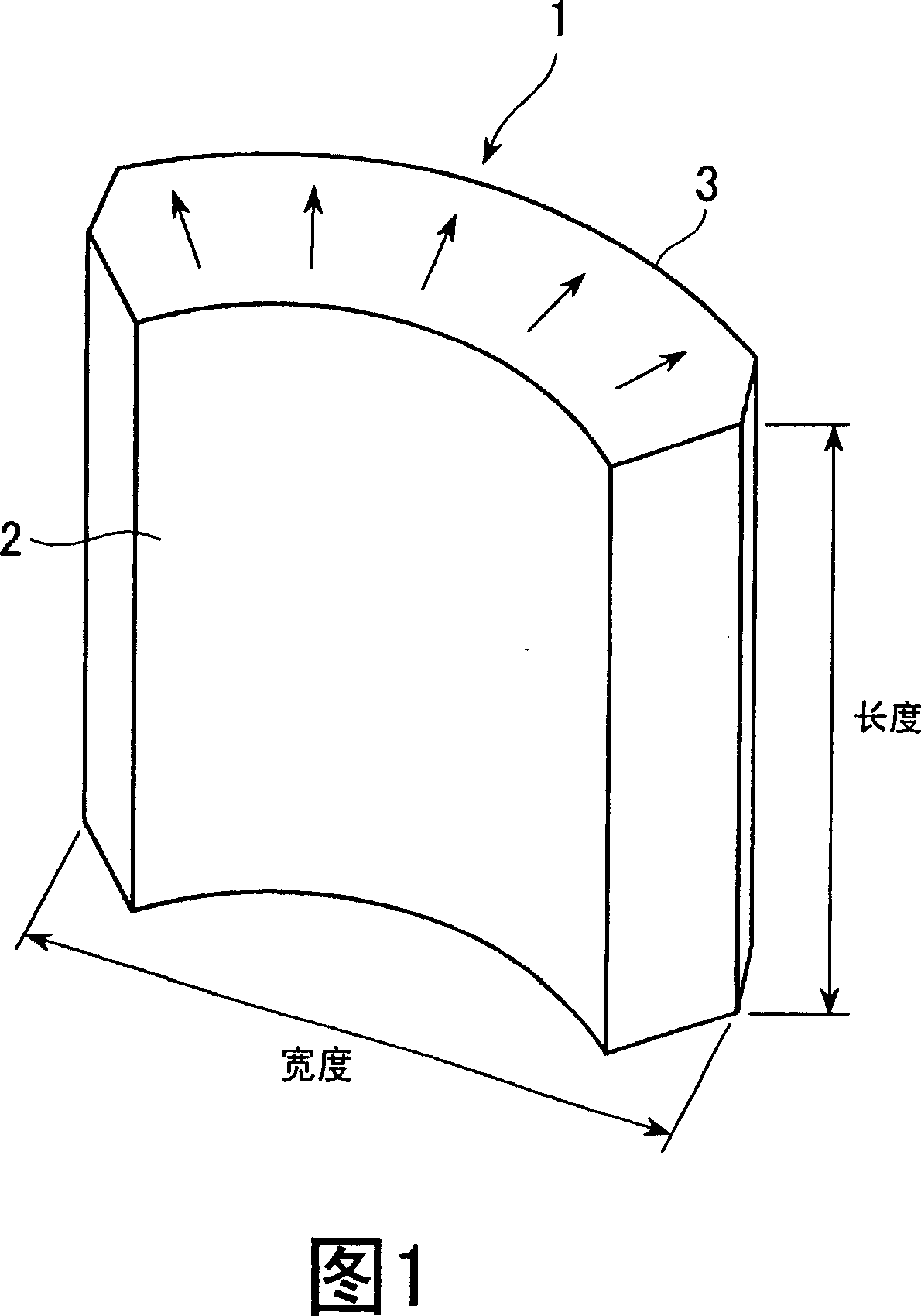
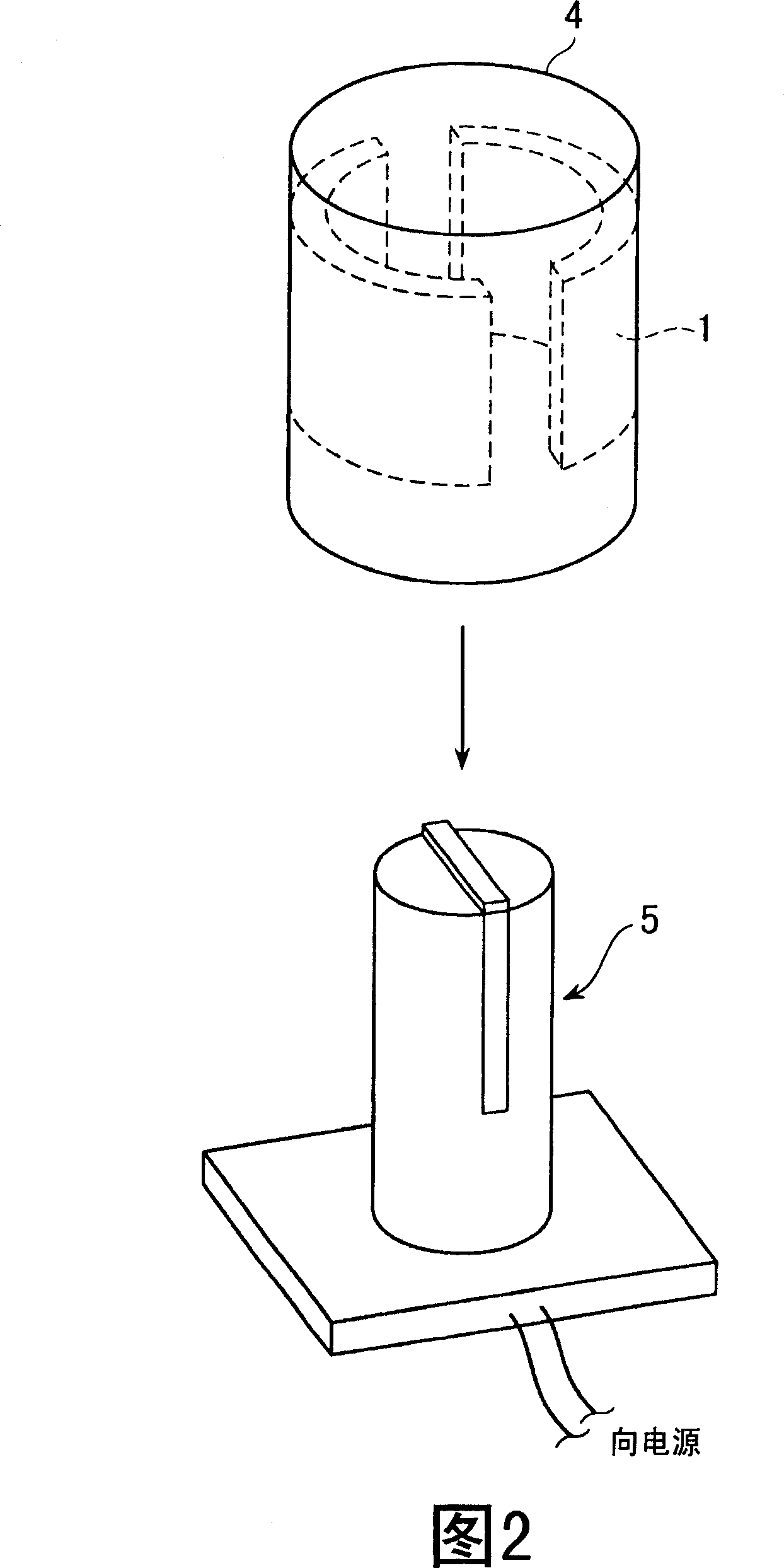
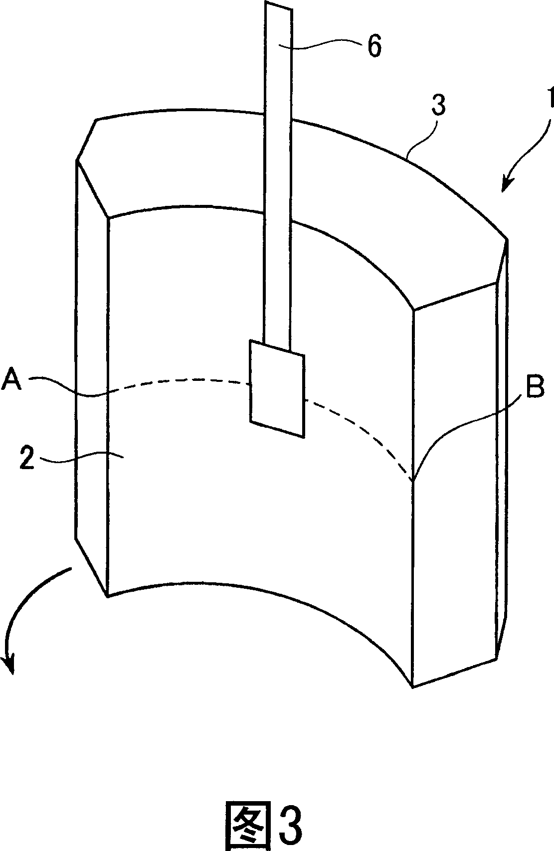
The present invention provides a dry-formed anisotropic ferrite magnet capable of reducing cogging torque and torque ripple. The anisotropic ferrite magnet has an inner peripheral surface and an outer peripheral surface opposite to the inner peripheral surface, has an arc-shaped cross section, and has magnetic anisotropy in its radial direction and is formed by dry molding, and is characterized in that , in the Bd distribution curve with the measurement region length in the circumferential direction of the inner peripheral surface or the outer peripheral surface as the abscissa and the surface magnetic flux density Bd as the vertical axis, the maximum value and the minimum value of the above-mentioned Bd in the above-mentioned inner peripheral surface are set Respectively Bdi(max), Bdi(min), when the maximum value and minimum value of the above-mentioned Bd in the above-mentioned outer peripheral surface are respectively Bdo(max), Bdo(min), satisfy Ro=Bdo(min)/Bdo(max )≥0.5, and Ri/Ro={Bdi(min)/Bdi(max)}/{Bdo(min)/Bdo(max)}<1.0.
Description
technical field [0001] The present invention relates to an arc-shaped ferrite magnet with anisotropy in the radial direction and a motor using the ferrite magnet produced by a dry forming method. Background technique [0002] High performance, small size, and light weight are required for motors used in home appliances, automotive electrical installations, and the like. Such a motor is a DC motor, and arc-shaped anisotropic ferrite magnets are used as magnets. These motors use magnets that are anisotropic with the radial direction being the easy axis. For these magnets, the surface magnetic flux density Bd on the inner peripheral surface side is required to be large and the distribution of the surface magnetic flux density Bd on the inner peripheral surface side to be uniform in the circumferential direction. If the fluctuation of the magnetic flux density Bd on the inner peripheral surface is large from the circumference to the upper surface, the cogging torque and torque...
Claims
Login to View More Application Information
Patent Timeline
 IPC IPC(8): H01F7/02H01F1/10H01F41/02
Inventor 增泽清幸永井秀和
Owner TDK CORPARATION
Features
- R&D
- Intellectual Property
- Life Sciences
- Materials
- Tech Scout
- Unparalleled Data Quality
- Higher Quality Content
- 60% Fewer Hallucinations
Learn More Browse by: Latest US Patents, China's latest patents, Technical Efficacy Thesaurus, Application Domain, Technology Topic, Popular Technical Reports.
© 2025 PatSnap. All rights reserved.Legal|Privacy policy|Modern Slavery Act Transparency Statement|Sitemap|About US| Contact US: help@patsnap.com


