
Hydraulic and mechanical automatic speed variator

A technology of automatic transmission and hydraulic machinery, applied in the direction of transmission, fluid transmission, mechanical equipment, etc., can solve the problems of high cost and complex production process, and achieve the effect of low production cost, improved comfort, and improved ride comfort.

Inactive Publication Date: 2007-10-17
范巨新
View PDF0 Cites 4 Cited by
  • Summary
  • Abstract
  • Description
  • Claims
  • Application Information

AI Technical Summary

Problems solved by technology

[0003] The purpose of the present invention is to overcome the disadvantages of complex production process and high cost of existing vehicle electronically controlled automatic transmissions, and provide a form of hydromechanical automatic transmission device

Method used


Image

  • Hydraulic and mechanical automatic speed variator
  • Hydraulic and mechanical automatic speed variator
  • Hydraulic and mechanical automatic speed variator

Examples


Embodiment Construction

[0034] The specific content of the present invention will be further described below in conjunction with the embodiments shown in the accompanying drawings.

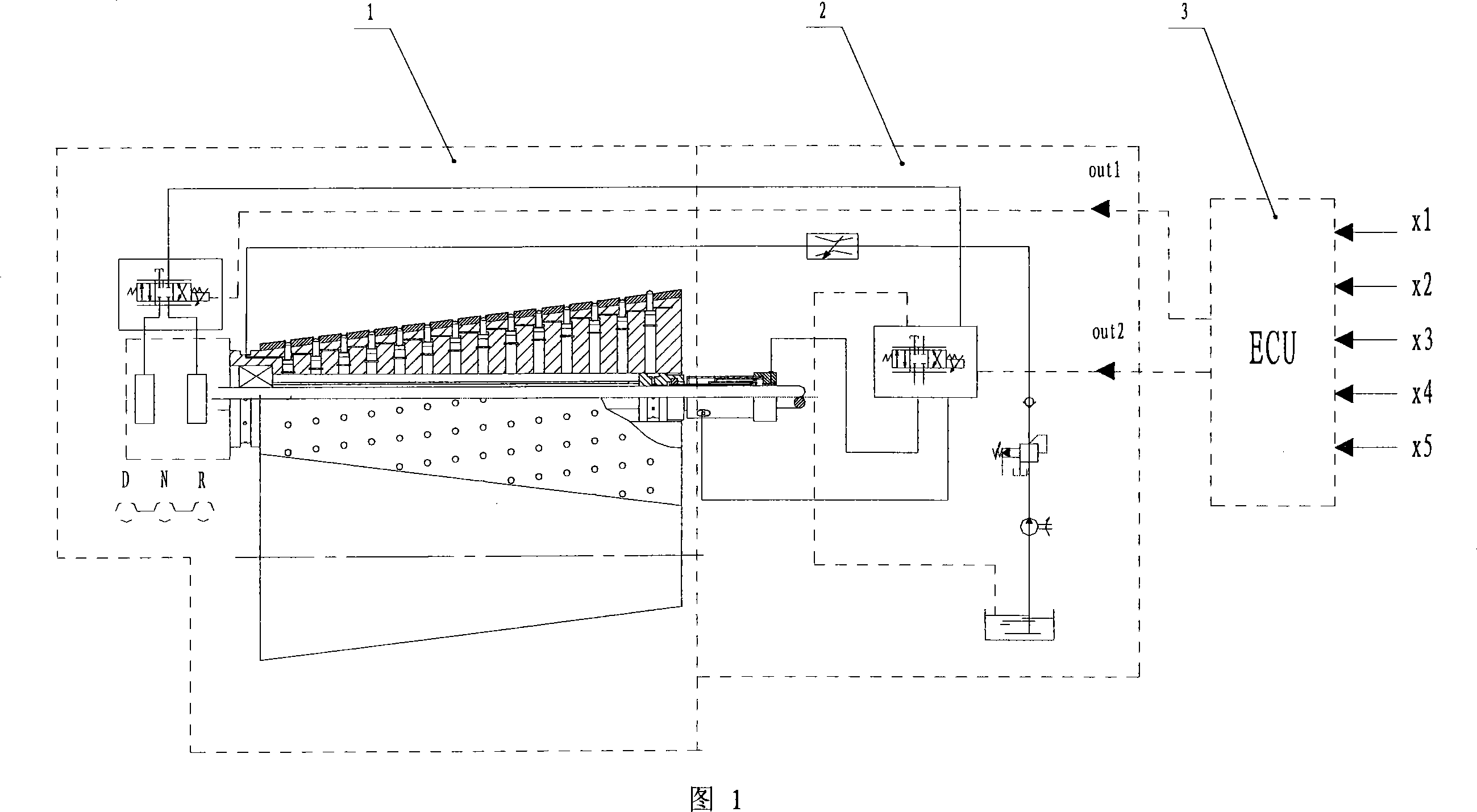
[0035] The hydromechanical automatic transmission device is mainly composed of a transmission part 1, a hydraulic control part 2 and a control unit 3. The said control unit 3 is connected with the transmission 1 and the hydraulic control part 2 respectively. The transmission part 1 is composed of a gear box 4, a driving frustum body 5, a driven frustum body 6, a shift selection cylinder 7, and a shift piston 8.

[0036] The technical solution provided by the invention has the following main technical features:

[0037] A. The external structures of the two truncated cones are consistent, and they are installed upside down on the axes parallel to each other. The surfaces of the two truncated cones are in contact, and the plunger in one of the truncated cones is moved out of its surface to make it Interlocking with anoth...


PUM


Abstract

The present invention relates to vehicle electronic control automatic speed variator field, especially relates to a hydraulic automatic mechanical speed variator device. The object is to conquer the fault that the existing vehicle electronic control automatic speed variator is complex in manufacturing technique and high in cost. The device is composed of a speed variator part, a hydraulic control part and a control unit, the control unit is connected to the speed variator and the hydraulic control part; the speed variator part includes an initiative awl table and a driven awl table that are accordance in external structure, inverse with each other, mounted with the surfaces are contacting with each other and parallel in axes, a gear box mounted at the left end of the initiative awl table and a gear shifting piston mounted in the internal main oil channel of the initiative awl table and a gear shifting selecting cylinder for driving the gear shifting piston, the initiative awl table and the driven awl table are machined with plural round holes with same position and diameter, the round holes of the initiative awl table is mounted with plural groups of plungers that can protrudes from the external surface through the round holes, the plunger oil channel is connected to the internal main oil channel of the initiative awl table.

Description

technical field [0001] The invention relates to the field of electronically controlled automatic transmissions for vehicles, in particular to a hydromechanical automatic transmission device. Background technique [0002] Vehicle automatic transmissions have been widely used in cars and have been accepted by the majority of vehicle users. However, due to the complex production process and cumbersome production process of automatic transmissions for vehicles, only a small number of automobile manufacturers produce them, which increases the cost of automatic transmissions, and the higher cost burden directly falls on vehicle users. Therefore, its application is subject to certain restrictions. Contents of the invention [0003] The purpose of the present invention is to overcome the disadvantages of complex production process and high cost of the existing electronically controlled automatic transmission for vehicles, and provide a form of hydromechanical automatic transmissi...

Claims


Application Information

Patent Timeline
IPC IPC(8): F16H47/02
Inventor 范巨新范双陈玲
Owner 范巨新
Learn More