
Sliding block for mold and mold

A mold and slider technology, applied in the field of molds, can solve the problems of mold clamping and large friction resistance, and achieve the effect of preventing mold clamping and avoiding large friction.

Inactive Publication Date: 2007-10-17
HONG FU JIN PRECISION IND (SHENZHEN) CO LTD +1
View PDF2 Cites 3 Cited by
  • Summary
  • Abstract
  • Description
  • Claims
  • Application Information

AI Technical Summary

Problems solved by technology

[0003] However, in the current mold structure, the contact between the slider and other mold components adopts a surface contact method. This contact method has a large frictional resistance, and even the phenomenon of mold jamming sometimes occurs

Method used


Image

  • Sliding block for mold and mold
  • Sliding block for mold and mold
  • Sliding block for mold and mold

Examples


Embodiment Construction

[0015] The present invention will be described in further detail below in conjunction with the accompanying drawings.

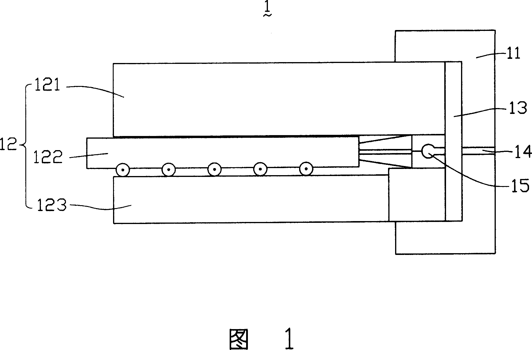
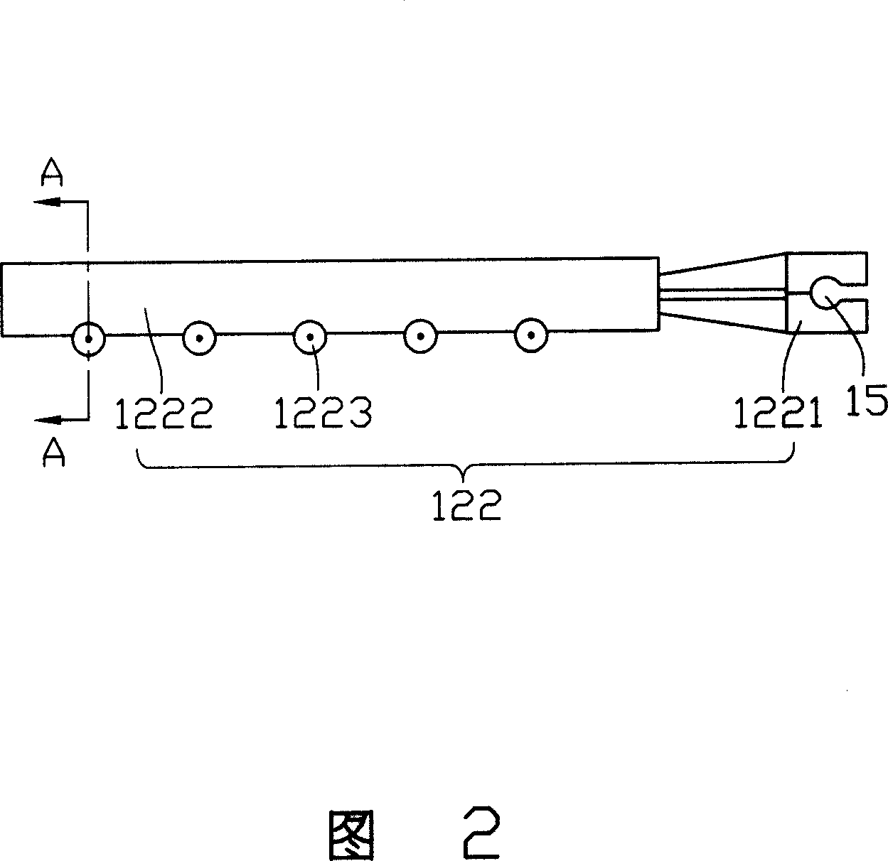
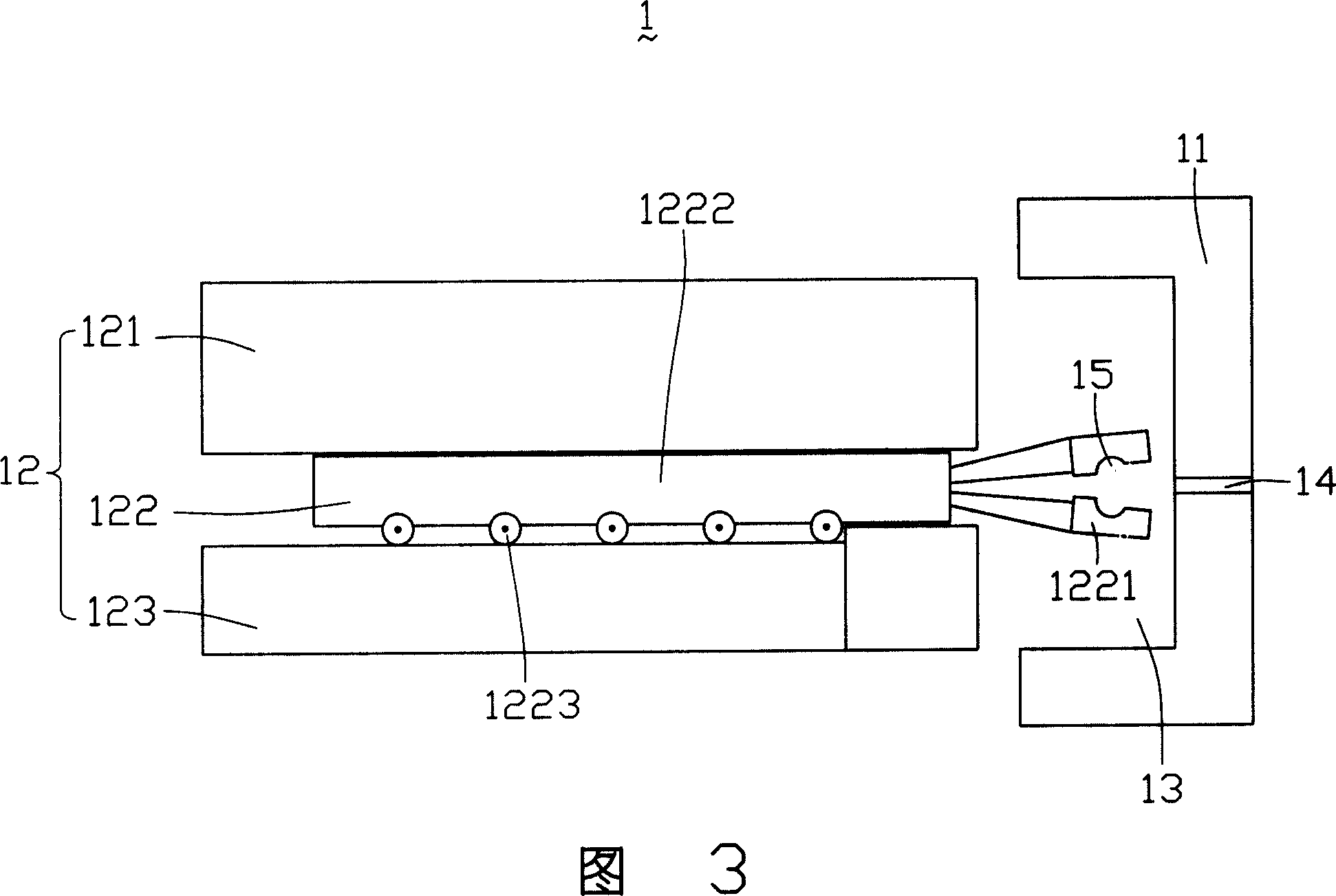
[0016] Please refer to FIG. 1 and FIG. 2 , the mold 1 according to the first embodiment of the present invention includes: a male mold 11 , a female mold 12 , a cavity 13 and an injection port 14 located on the male mold 11 . Wherein, the master mold 12 includes an upper pressing plate 121 , a sliding block 122 and a bottom plate 123 sequentially from top to bottom. The slider 122 includes a slider body 1222 whose upper surface is in sliding contact with the upper pressing plate 121 , and at least one rolling device 1223 disposed on the lower surface of the slider body 1222 .

[0017] In this embodiment, the slider 122 further includes a forming portion 1221 , the forming portion 1221 has a cavity 15 communicating with the cavity 13 and is integrally formed with the slider body 1222 . The forming part 1221 is an elastic device, and when the forming part 1221...


PUM


Abstract

The present invention relates to a slider used for a die and a die thereof. A rolling device is arranged on the body of the slider or the die, thereby, the excellent relative slip between the slider and the die can be realized by means of the rolling device, and the unhealthy tendency of blocking of the die can be avoided.

Description

【Technical field】 [0001] The invention relates to a mold assembly, in particular to a slide block for a mold and a mold. 【Background technique】 [0002] In recent years, with the rapid development of the automobile and household electrical appliance industries, the demand for molds, especially large, precise, complex and long-life molds, is increasing, and the performance requirements for mold standard parts are also getting higher and higher. Among them, the slider is widely used in molds because of its adjustable processing of undercuts or side holes. [0003] However, in the current mold structure, the contact between the slider and other mold components adopts a surface contact method. This contact method has a large frictional resistance, and sometimes even die jamming occurs. 【Content of invention】 [0004] In view of this, it is necessary to provide a slide block and mold for a mold that has small frictional resistance and can be safely removed from the mold. [0...

Claims


Application Information

Patent Timeline
Patent Type & Authority Applications(China)
IPC IPC(8): B29C33/34B29C33/44
Inventor 杜健生
Owner HONG FU JIN PRECISION IND (SHENZHEN) CO LTD
Learn More