
Machine barrel with grooves

A grooved and barrel technology, applied in the field of grooved barrels, can solve the problems of difficulty in blanking, affecting extrusion volume, low resin output, etc., to improve conveying efficiency, increase service life, and reduce friction and heat generation Effect

Pending Publication Date: 2022-04-19
ZHANGJIAGANG BEIER MACHINERY
View PDF0 Cites 0 Cited by
  • Summary
  • Abstract
  • Description
  • Claims
  • Application Information

AI Technical Summary

Problems solved by technology

[0002] Plastic products are more and more applied to various fields. Replacing steel with plastic and recycling has become a development trend. With the continuous development of the market, the demand for plastic products in the market is increasing. At the same time, the quality of plastic products The requirements are getting higher and higher. At present, the barrels of single-screw extruders used in the production of plastic products have the following disadvantages: 1. The energy consumption ratio is low, and the output of resin extruded with the same energy consumption is low; Unstable and easy to slip, which leads to unstable dragging and friction transportation of materials, resulting in poor output stability of the extruder; 3. The overheating of the first zone of the barrel is serious on the spot, because the material is still there when it enters the first zone of the barrel through the feeding chute. If it is in granular form, the frictional temperature rises rapidly at this time, causing the barrel in the first zone to not cool down, which affects the extrusion volume; 4. At present, the service life of the feeding chute of the barrel of the single-screw extruder is low and the wear is fast, resulting in The maintenance cost of the equipment is high; 5. The current barrel feeding groove is sensitive to the size and shape of the resin particles. During use, it is difficult to feed some resin particles, and the resin particles slip in the barrel groove and do not move forward. Transportation, resulting in a drop in output and poor adaptability

Method used


Image

  • Machine barrel with grooves

Examples


Embodiment Construction

[0013] In order to more clearly illustrate the technical solutions in the embodiments of the present invention or the prior art, the following will briefly introduce the drawings that need to be used in the description of the embodiments or the prior art. Obviously, the accompanying drawings in the following description are only These are some embodiments of the present invention. For those skilled in the art, other drawings can also be obtained according to these drawings without any creative effort.

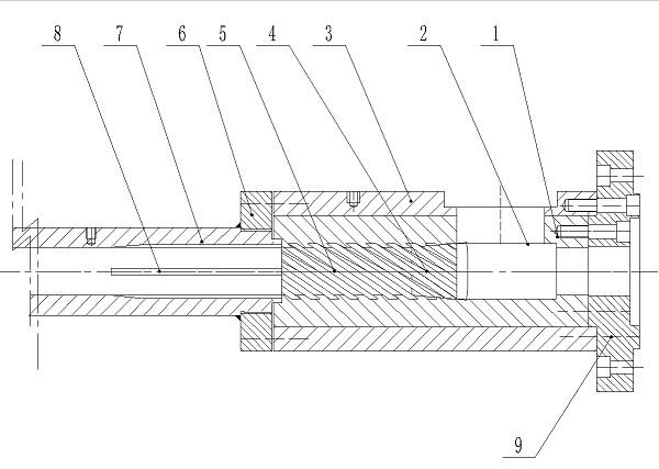
[0014] see as figure 1 As shown, this specific embodiment adopts the following technical scheme: it includes a blanking water jacket 1, a blanking section 2, a water jacket jacket 3, a tapered groove section 4, a conveying groove section 5, a connecting flange 6, and a barrel Straight section 7, barrel groove section 8 and large flange 9; the outside of the blanking water jacket 1 is in interference fit with the water jacket jacket 3, and the outer wall of the blanking water ja...


PUM

PropertyMeasurementUnit
Taperaaaaaaaaaa

Abstract

The invention discloses a groove type machine barrel, and relates to the technical field of plastic extrusion machinery. The outer portion of the discharging water jacket is in interference fit with the water jacket outer sleeve, a plurality of cooling water grooves are machined in the outer wall of the discharging water jacket, the discharging water jacket is sequentially provided with a discharging section, a tapered groove section and a conveying groove section from right to left, and a plurality of spiral grooves are formed in the conveying groove section. One end of the blanking water jacket and one end of the water jacket jacket are connected with a machine barrel straight section through connecting flanges; a plurality of machine barrel groove sections are arranged on the inner wall of one end of the machine barrel straight section; the other end of the blanking water jacket and the other end of the water jacket outer sleeve are connected with the large flange through screws. The conveying efficiency of the resin in the straight section of the machine barrel is greatly improved, the resin cannot be accumulated in the first area of the straight section of the machine barrel, high friction and ultrahigh temperature of the resin in the first area of the straight section of the machine barrel are avoided, and therefore the service life of the machine barrel is prolonged, the resin extrusion stability is improved, friction heating is reduced, and the energy consumption ratio is increased.

Description

technical field [0001] The invention relates to the technical field of plastic extrusion machinery, in particular to a grooved barrel. Background technique [0002] Plastic products are more and more used in various fields, plastic instead of steel, recycling has become a development trend, with the continuous development of the market, the market demand for plastic products is increasing, while the quality of plastic products The requirements are getting higher and higher. At present, the barrels of single-screw extruders used in the production of plastic products have the following disadvantages: 1. The energy consumption ratio is low, and the output of resin extruded with the same energy consumption is low; Unstable and easy to slip, which leads to unstable dragging and friction transportation of materials, resulting in poor output stability of the extruder; 3. The overheating of the first zone of the barrel is serious on the spot, because the material is still there when...

Claims


Application Information

Patent Timeline
IPC IPC(8): B29C48/685
CPCB29C48/686
Inventor 何德方蒋伟
Owner ZHANGJIAGANG BEIER MACHINERY
Learn More